Collision energy-absorbing material for vehicle and collision energy-absorbing structure of vehicle using the material
- Summary
- Abstract
- Description
- Claims
- Application Information
AI Technical Summary
Benefits of technology
Problems solved by technology
Method used
Image
Examples
second embodiment
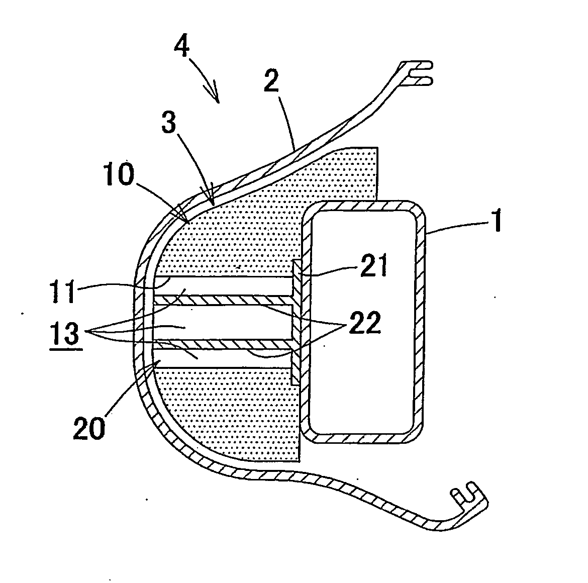
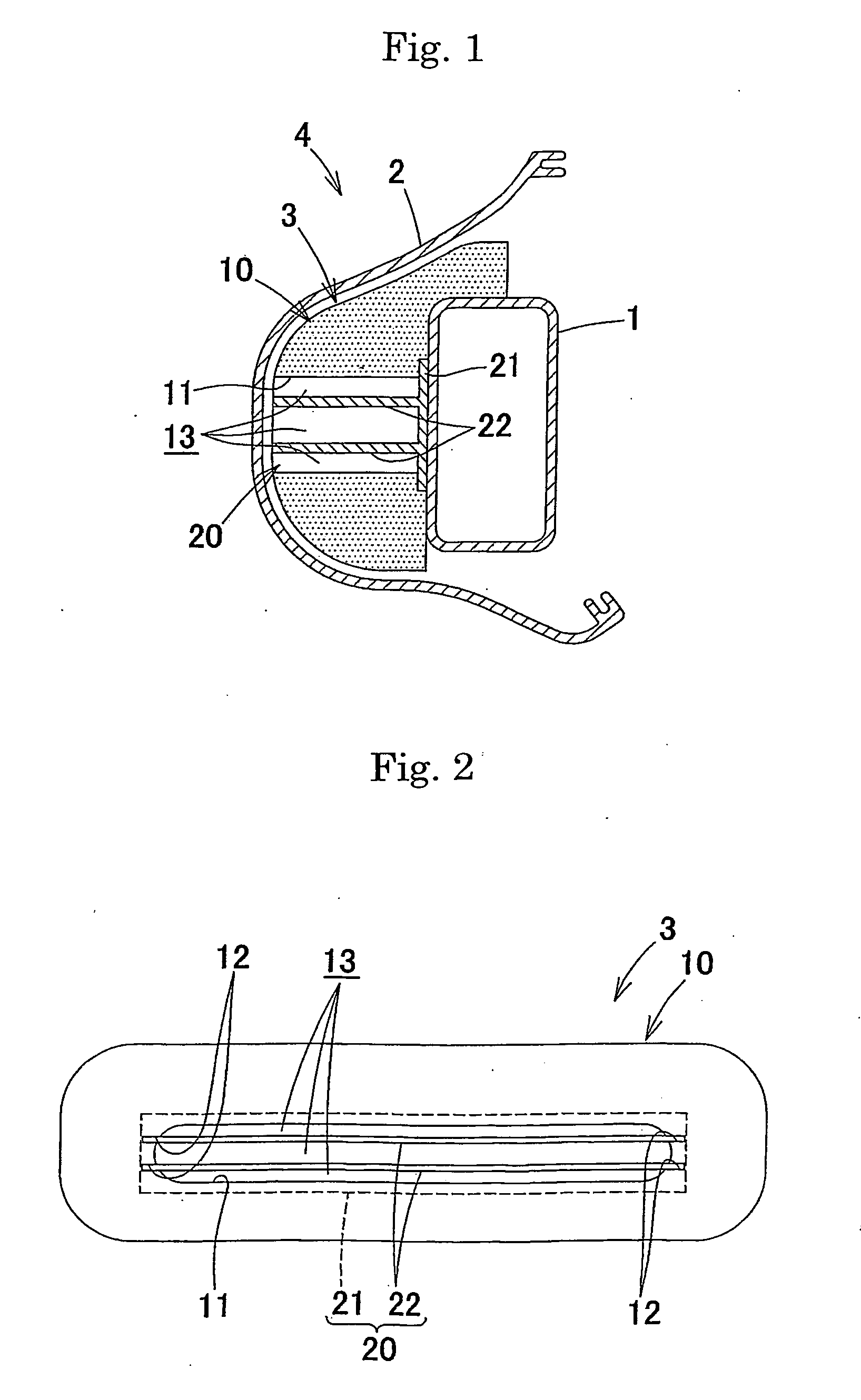
[0115] In this second embodiment, the first vehicle impact energy absorbing member in accordance with the present invention is applied to a front side door of a motor vehicle.
[0116] Description will be made of the front side door 40 with reference to FIGS. 21 and 22. A side door main body 43 constituted by a door outer panel 41 and a door inner panel 42 and closed as viewed in section is provided and a door trim 46 is provided on the compartment side of the side door main body 43. The door trim 46 has an upper projecting portion 44 and a lower projecting portion 45 which extend through its entire length in the vehicle front-rear direction, and which are disposed in correspondence with the breast and waist of a passenger so as to project on the compartment side. An upper impact energy absorbing member 47 is provided in the upper projecting portion 44 between the door inner panel 42 and the door trim 46, while a lower impact energy absorbing member 48 is provided in the lower project...
third embodiment
[0122] In this third embodiment, the first vehicle impact energy absorbing member in accordance with the present invention is applied to a front pillar 70 of a motor vehicle. Description will be made of the front pillar 70 with reference to FIGS. 23 and 24. A pillar main body 74 constituted by a pillar outer panel 71 and a pillar inner panel 72 and closed as viewed in section is provided and a pillar trim 73 is provided on the compartment side of the pillar main body 74. An impact energy absorbing member 75 is provided between the pillar inner panel 72 and the pillar trim 73.
[0123] The impact energy absorbing member 75 has basically the same construction as that of the impact energy absorbing member 3 in the above-described first embodiment, but differs in size from the same. The corresponding impact energy absorbing member can be understood as capable of being mounted on the front pillar 70 if the bumper reinforcing member 1 in the first embodiment is reread as pillar inner panel ...
fourth embodiment
[0131] In this fourth embodiment, the second vehicle impact energy absorbing member in accordance with the present invention is applied to a front bumper of a motor vehicle. As shown in FIG. 34, a bumper reinforcing member 101 extending in the vehicle width direction is provided in a front end portion of a vehicle body; a bumper facer 102 is provided on the front side of the bumper reinforcing member 101 so as to cover the same; and an impact energy absorbing member 103 is mounted between the bumper reinforcing member 101 and the bumper facer 102. A front bumper 104 is constituted by the bumper facer 102 and the impact energy absorbing member 103. An impact load at the time of front-on collision is transferred to the impact energy absorbing member 103 through the bumper facer 102 and is received by these two members while these members are being deformed by the impact load. When a larger impact load acts on the bumper, the impact load acts on the bumper reinforcing member 101 to be ...
PUM
 Abstract
Description
Claims
Application Information
 - R&D
- Intellectual Property
- Life Sciences
- Materials
- Tech Scout
- Unparalleled Data Quality
- Higher Quality Content
- 60% Fewer Hallucinations
Browse by: Latest US Patents, China's latest patents, Technical Efficacy Thesaurus, Application Domain, Technology Topic, Popular Technical Reports.
© 2025 PatSnap. All rights reserved.Legal|Privacy policy|Modern Slavery Act Transparency Statement|Sitemap|About US| Contact US: help@patsnap.com


