Lifting ladder for indoor building construction

A technology for building construction and elevators, which is applied in the direction of hoisting devices, safety devices for lifting equipment, etc., and can solve problems such as unusable elevators, low stability of elevators, and unsafe construction personnel.

Inactive Publication Date: 2020-10-27
CHONGQING VOCATIONAL INST OF ENG
View PDF0 Cites 0 Cited by
  • Summary
  • Abstract
  • Description
  • Claims
  • Application Information

AI Technical Summary

Problems solved by technology

[0002] During indoor construction, elevators are often used. Most of the current elevators use cylinders as driving components to drive the ladder up and down. However, in the process of building construction, such as the process of building walls, the frame structure of the buil

Method used


Image

  • Lifting ladder for indoor building construction
  • Lifting ladder for indoor building construction

Examples


Embodiment 1

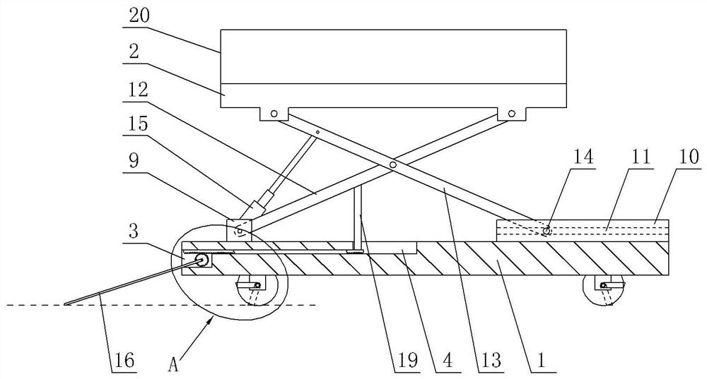
[0025] Embodiment one is basically as attached figure 1 , 2 Shown: as figure 1 A lift for indoor construction is shown, comprising a base 1, a support plate 2 and a lifting and stabilizing mechanism. The lifting and stabilizing mechanism includes a lifting unit and a stabilizing unit; A second groove 4 is formed on the surface, a slideway 5 is formed in the base 1 , and the first groove 3 communicates with the second groove 4 through the slideway 5 .

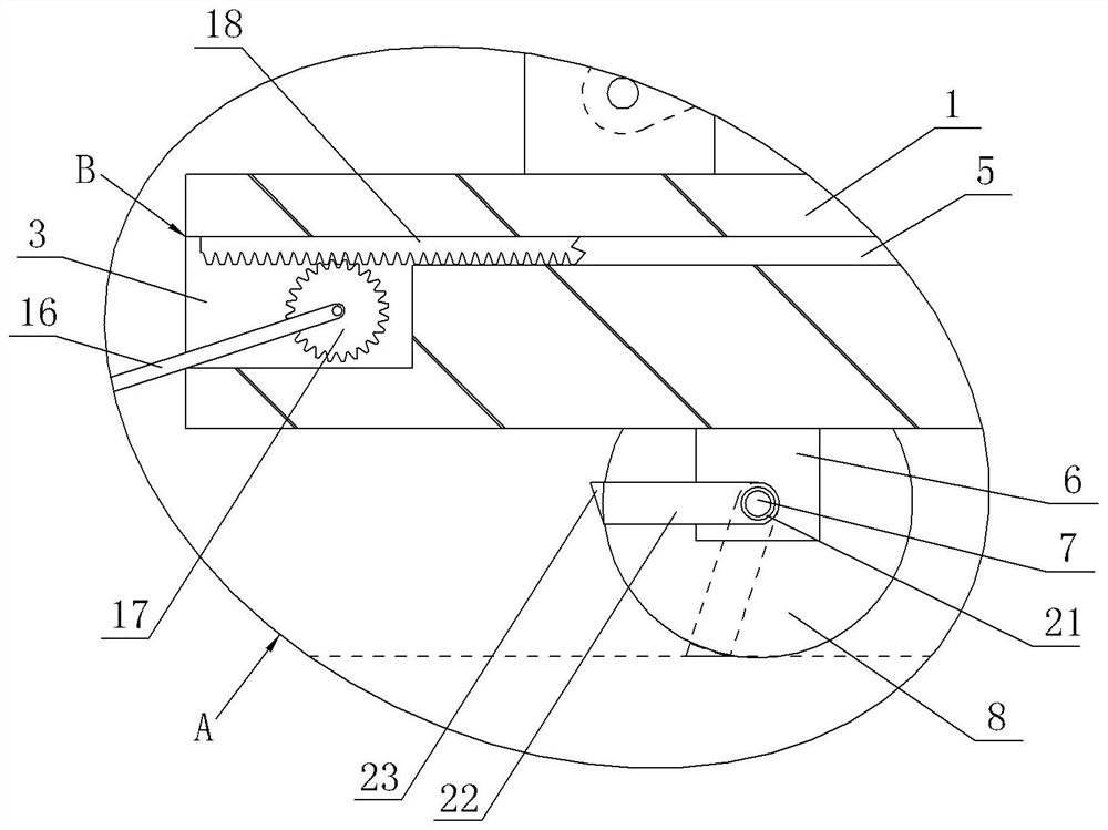
[0026] The bottom of the base 1 is provided with a traveling mechanism, and the traveling mechanism includes two walking units, such as figure 2 As shown, each walking unit includes a support block 6, a support shaft 7 and two rollers 8, the support block 6 is welded to the lower surface of the base 1, a through hole is provided on the support block 6, and the support shaft 7 and the side wall of the through hole Rotationally connected, the two rollers 8 are respectively coaxially fixedly assembled on the front and rear ends...

Embodiment 2

[0038] On the basis of Example 1, as figure 2 As shown, at least one locking mechanism is also included, that is, there can be one locking mechanism, and now the locking mechanism is located at the right end of the base 1; the number of locking mechanisms in this embodiment is two, and each locking mechanism includes a sleeve The barrel 21 and at least one locking unit. In this embodiment, each locking mechanism includes a locking unit, and the locking unit is located in front of the support block 6 .

[0039] Specifically, each locking unit includes a rotating block 22 and a locking block 23, the rotating block 22 and the locking block 23 are welded, and the top view of the rotating block 22 and the locking block 23 is "L" shaped; the sleeve 21 passes through The outer wall of the support block 6 and the sleeve 21 is welded with the support block 6, the support shaft 7 is rotatably connected with the sleeve 21, the length of the support shaft 7 is greater than the length of ...


PUM


Abstract

The invention relates to the construction field, in particular to a lifting ladder for indoor building construction. The lifting ladder for indoor building construction comprises a base, a supportingplate and a lifting and stabilizing mechanism. The lifting and stabilizing mechanism comprises a lifting unit and a stabilizing unit. A first groove is arranged at the end of the base. The upper surface of the base is provided with a second groove. A slide way is arranged in the base. The first groove communicates with the second groove through the slide way. The lifting unit comprises a first lifting bar and a second lifting bar. The stabilizing unit comprises a stabilizing frame, a gear column, a rack and a supporting bar, wherein the gear column is rotationally arranged in the first groove,the two ends of the stabilizing frame are fixedly connected with end faces of the gear column correspondingly, the rack is arranged in the slide way in a sliding manner, the rack is meshed with the gear column, the lower end of the supporting bar is fixedly connected with the rack in the second groove, and the upper end of the supporting bar can make contact with the first lifting bar. By the adoption of the technical scheme, the lifting ladder can be used without a power source, and the stability is high.

Description

technical field [0001] The invention relates to the field of construction, in particular to an elevator for indoor building construction. Background technique [0002] During indoor construction, elevators are often used. Most of the current elevators use cylinders as driving components to drive the ladder up and down. However, in the process of building construction, such as the process of building walls, the frame structure of the building is formed. If the power supply has not been installed, the cylinder cannot be put into use, thus causing the elevator to be unusable; moreover, the elevator has low stability during use and is prone to rollover, which cannot guarantee the safety of construction workers. Contents of the invention [0003] The object of the present invention is to provide an elevator for indoor building construction that can be used without power supply and has high stability. [0004] In order to achieve the above object, the technical solution of the ...

Claims


Application Information

Patent Timeline
IPC IPC(8): B66F11/04B66F17/00
CPCB66F11/042B66F17/006
Inventor 马相明彭军
Owner CHONGQING VOCATIONAL INST OF ENG
Why Eureka
Try Eureka