Quick take-up and pay-off device with adjustable length and width suitable for different types of cable reels and its usage method

A technology for retracting and paying off a wire device and a cable reel, which is applied in the field of auxiliary equipment and can solve the problems of low operation efficiency, time-consuming and labor-intensive pulling of wires, time-consuming and labor-intensive driving, etc.

Active Publication Date: 2017-01-25
NANYANG POWER SUPPLY COMPANY OF STATE GRID HENAN ELECTRIC POWER
View PDF9 Cites 0 Cited by
  • Summary
  • Abstract
  • Description
  • Claims
  • Application Information

AI Technical Summary

Problems solved by technology

Its shortcoming is that a crane is required to hoist the cable reel on the bracket during use, which is time-consuming and labor-intensive and requires the cooperation of multiple people.
Its shortcoming is that the cable reel needs to be frequently pushed between the rollers of the platform during use, and the staff needs to fix the platform on the ground and ensure that the platforms of the two bases are parallel and orderly so that the cable reel can be pushed smoothly. Between the rollers on the platform, frequent replacement of cable reels of different specifications requires frequent adjustment of the distance between platforms and disassembly and fixing of the platform, which is extremely time-consuming and labor-intensive to use; at the same time, due to the weight of the cable reel, multiple personnel are required to push it In the process of pushing, it is easy to cause the cable reel to fall out and hurt others. Usually, at least 5 workers are required. The push is time-consuming and laborious. It takes at least 3 people to remove the cable reel and replace it with another cable reel of a different type. Hours, the work efficiency is low, and it takes time and effort to pull the wire to rotate

Method used


Image

  • Quick take-up and pay-off device with adjustable length and width suitable for different types of cable reels and its usage method
  • Quick take-up and pay-off device with adjustable length and width suitable for different types of cable reels and its usage method
  • Quick take-up and pay-off device with adjustable length and width suitable for different types of cable reels and its usage method

Examples


Embodiment 1

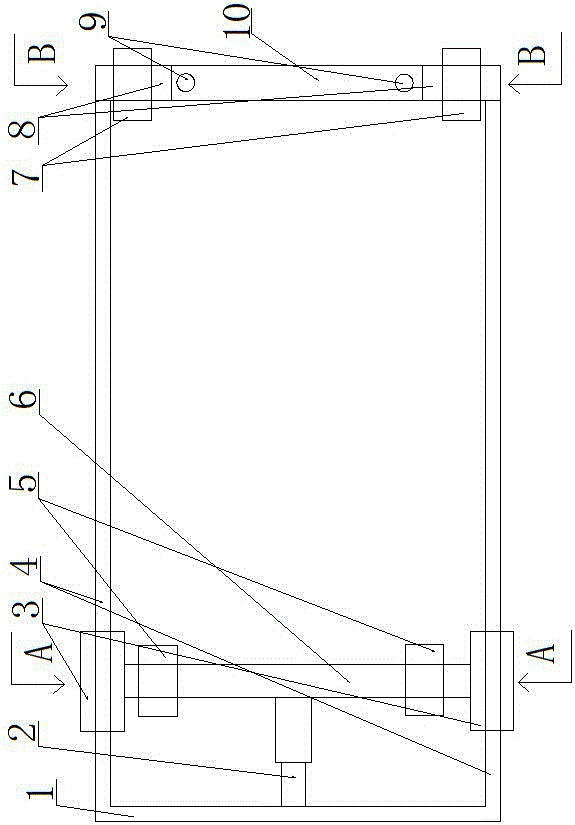
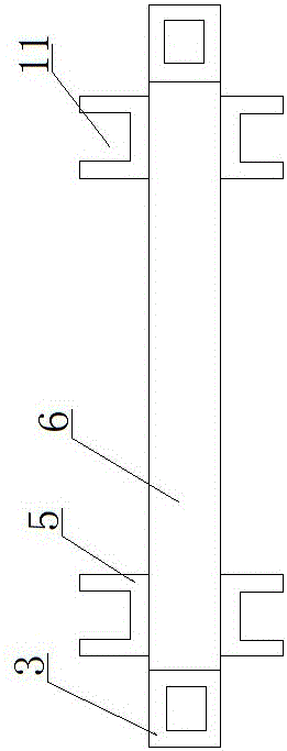
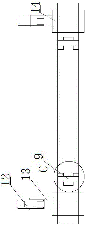
[0031] Embodiment 1: as figure 1 , 2, 3, 4, 5, and 6, a quick take-up and release device with adjustable length and width suitable for different types of cable reels, including a U-shaped frame body, and universal self-locking devices are provided under the four corners of the U-shaped frame body Roller 15, the inner side of two cross bars 4 free ends of described U-shaped frame body is provided with the extension bar 8 that is perpendicular to cross bar 4, and described extension bar 8 ends are provided with intersecting connecting rod 10 that is hinged, and this connecting rod 10 The other end of the other end is intersected with the free end of another extension rod. Two cable reel sliding mechanisms 7 are set on the connecting rod. The length of the extension rod 8 is greater than the width of the cable reel sliding mechanism 7. The U-shaped The two cross bars 4 of the frame body are equipped with guide sleeves 3, and the guide sleeves 3 are connected by a fixed rod 6, an...

Embodiment 2

[0043] Embodiment 2: as figure 1 , 2 , 3, 4, 5, and 6, a quick take-up and release device with adjustable length and width suitable for different types of cable reels, including a U-shaped frame body, and universal self-locking devices are provided under the four corners of the U-shaped frame body Roller 15, the inner side of two cross bars 4 free ends of described U-shaped frame body is provided with the extension bar 8 that is perpendicular to cross bar 4, and described extension bar 8 ends are provided with intersecting connecting rod 10 that is hinged, and this connecting rod 10 The other end of the other end is intersected with the free end of another extension rod. Two cable reel sliding mechanisms 7 are set on the connecting rod. The length of the extension rod 8 is greater than the width of the cable reel sliding mechanism 7. The U-shaped The two cross bars 4 of the frame body are equipped with guide sleeves 3, and the guide sleeves 3 are connected by a fixed rod 6, a...

Embodiment 3

[0058] Embodiment 3: as figure 1 , 2 , 3, 4, 5, and 6, a quick take-up and release device with adjustable length and width suitable for different types of cable reels, including a U-shaped frame body, and universal self-locking devices are provided under the four corners of the U-shaped frame body Roller 15, the inner side of two cross bars 4 free ends of described U-shaped frame body is provided with the extension bar 8 that is perpendicular to cross bar 4, and described extension bar 8 ends are provided with intersecting connecting rod 10 that is hinged, and this connecting rod 10 The other end of the other end is intersected with the free end of another extension rod. Two cable reel sliding mechanisms 7 are set on the connecting rod. The length of the extension rod 8 is greater than the width of the cable reel sliding mechanism 7. The U-shaped The two cross bars 4 of the frame body are equipped with guide sleeves 3, and the guide sleeves 3 are connected by a fixed rod 6, a...


PUM


Abstract

The invention discloses a quick take-up and release device with adjustable length and width suitable for different types of cable reels and a method of use. The inner sides of the free ends of the two cross bars of the U-shaped frame body are provided with extension rods perpendicular to the cross bar, and the ends of the extension rods are provided with intersecting and hinged connecting rods. The other end of the connecting rod is connected to the free end of the other extension rod Cross socketing, two cable reel sliding mechanisms are set on the connecting rod, the length of the extension rod is greater than the width of the cable reel sliding mechanism, guide sleeves are set on the two cross bars of the U-shaped frame body, The guide sleeves are connected by a fixed rod, and two driving rollers rotatably connected to the fixed rod are set on the fixed rod. An annular groove is provided on the peripheral side of the driving roller for the cable reel to snap into. The fixed rod The center of one side is connected with the center of the vertical bar of the U-shaped frame body through a hydraulic push rod.

Description

technical field [0001] The invention belongs to the technical field of auxiliary equipment used by electricians when erecting power lines, and in particular relates to a quick take-up and release device with adjustable length and width suitable for different types of cable reels and a use method. Background technique [0002] The power line product is a power line reel that winds the power line on the reel. When erecting high-altitude power lines, a large number of power lines are used. The power line reel is large in size and heavy, and the reel must be rotated when the wire is released. In order to use the power line reel to pay out the wires, the power line reel should be placed on the power line pay-off rack when paying out the wires. The power line pay-off frame is mainly used to support the power line reel for easy pay-out. [0003] In the construction of the substation secondary system, the workload of cable laying occupies the main construction time. The current ca...

Claims


Application Information

Patent Timeline
Patent Type & Authority Patents(China)
IPC IPC(8): H02G1/02H02G11/02
Inventor 尚光伟王顺王建磊李巍龚正国顾瑛
Owner NANYANG POWER SUPPLY COMPANY OF STATE GRID HENAN ELECTRIC POWER
Why Eureka
Try Eureka