
Backlight assembling device

A technology of assembly device and backlight, applied in packaging, transportation and packaging, conveyor objects, etc., can solve problems such as reducing processing efficiency, increasing product production costs, and difficult to ensure product quality.

Active Publication Date: 2020-10-27
苏州工业园区欣隆电热仪器有限公司
View PDF8 Cites 0 Cited by
  • Summary
  • Abstract
  • Description
  • Claims
  • Application Information

AI Technical Summary

Problems solved by technology

However, since the process of removing the film on both sides is relatively complicated and requires high precision, it is difficult to use automatic processing equipment to complete it directly, so it often requires manual operations by staff. On the one hand, it consumes a lot of manpower, material resources and time. It reduces the efficiency of processing and increases the cost of product production; on the other hand, the precision of manual operation is often low, making it difficult to guarantee the quality of products and prone to defective products

Method used


Image

  • Backlight assembling device
  • Backlight assembling device
  • Backlight assembling device

Examples


Embodiment Construction

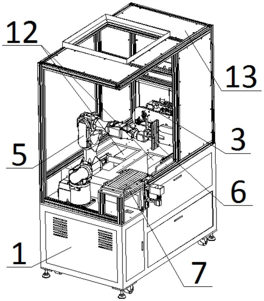
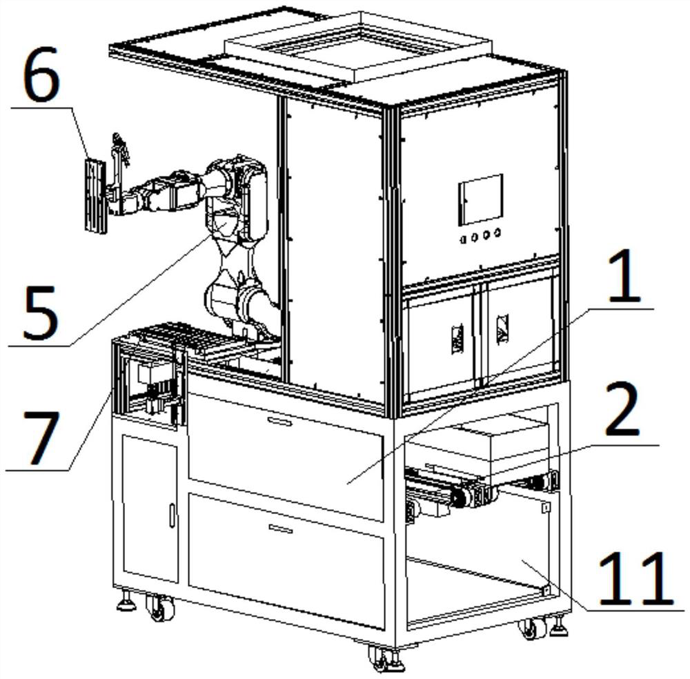
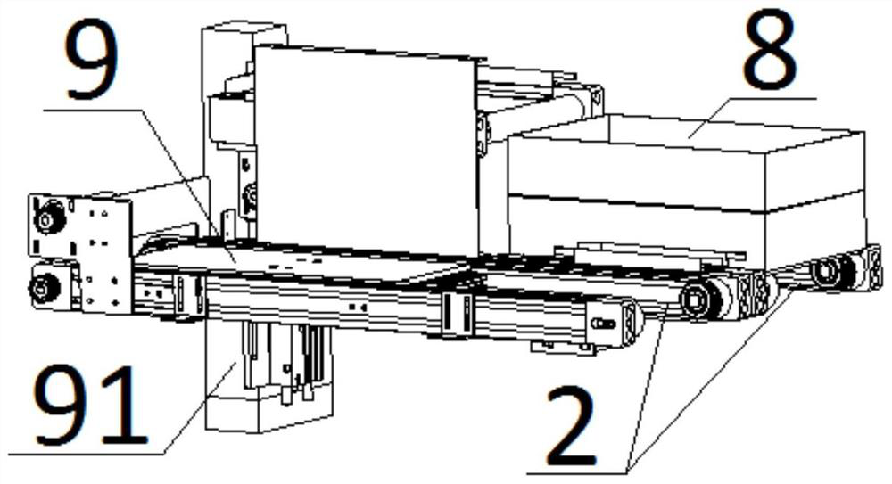
[0028] The present invention will be described in further detail below in conjunction with the accompanying drawings.

[0029] figure 1 Schematically shows the structure of a backlight assembly device according to an embodiment of the present invention, figure 2 shown figure 1 Another angle structure of a backlight assembly device in image 3 shown figure 1 The structure of the parallel drive belt in, Figure 4 shown figure 1 The structure of the upper block mechanism in Figure 5 shown figure 1 Part of the structure related to the suction plate in Figure 6 shown figure 1 Partial structure related to the adsorption mechanism in . Such as Figure 1-6 As shown, the device includes a roughly square workbench 1 on which other main mechanisms are arranged. Each corner of the bottom of the workbench 1 is provided with support parts, and each support part includes switchable feet and rollers to facilitate the stable placement and flexible movement of the workbench 1 and ...


PUM


Abstract

The invention discloses a backlight assembling device. The device comprises a working table, a parallel conveying belt, a block feeding mechanism, a manipulator and a sucking mechanism. A side openingis formed in one side surface of the working table, and a top opening is formed in the top surface of the working table; the parallel conveying belt is mounted in the working table, one ends of the parallel conveying belt is located at the side opening, and the other end of the parallel conveying belt is located below the top opening; the block feeding mechanism is mounted on the top surface of the working table and located over the parallel conveying belt, and stripping blocks are arranged; a sucking plate and a chuck are mounted on the manipulator; and the sucking mechanism is mounted on the working table. The backlight assembling device can achieve work of automatically removing protective film from the two sides of a to-be-attached film material and attaching the film material to a product, on the one hand, the manpower, material resources and time are greatly saved, the machining efficiency is improved, and the product production cost is reduced; and on the other hand, the automatic machining accuracy is high, and thus the product quality is guaranteed.

Description

technical field [0001] The invention relates to the field of processing equipment, in particular to a backlight assembly device. Background technique [0002] In the process of processing and manufacturing some mechanical and electrical products, it is often necessary to go through the step of attaching film materials to the products, and sometimes the attached film materials need to be specially made and then pasted and assembled. In the process of manufacturing the film material, in order to ensure the safety and integrity of the film material, it is often necessary to cover a layer of protective film on both sides of the film material before processing. When the film material is finished and needs to be attached to the product, the protective film on each side of the film material needs to be removed first, and then the lamination work is carried out. However, because the process of removing the film on both sides is relatively complicated and requires high precision, it...

Claims


Application Information

Patent Timeline
IPC IPC(8): F16B11/00B65B69/00B65G47/90
CPCB65B69/00B65G47/90F16B11/006
Inventor 刁仁华陈克文刘翀
Owner 苏州工业园区欣隆电热仪器有限公司
Learn More