Shift range control device
A control device and gear technology, which is applied in transmission control, components with teeth, belts/chains/gears, etc., can solve problems such as reducing the accuracy of judgment, incorrect gear switching, and wrong judgment of gears, etc.
- Summary
- Abstract
- Description
- Claims
- Application Information
AI Technical Summary
Problems solved by technology
Method used
Image
Examples
no. 1 example
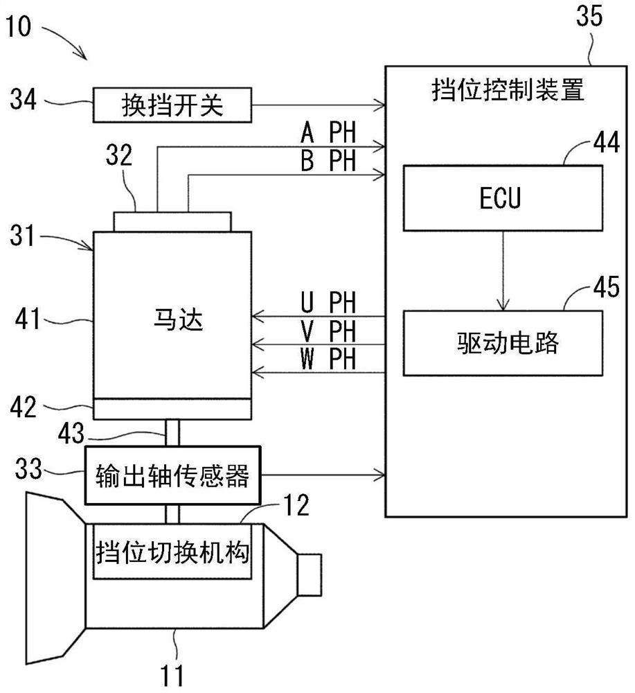
[0032] The gear control device according to the first embodiment is applied to a shift-by-wire system of a vehicle. Such as figure 1 As shown, the shift-by-wire system 10 is a system that electrically controls the gear shifting mechanism 12 of an automatic transmission 11 .
[0033]
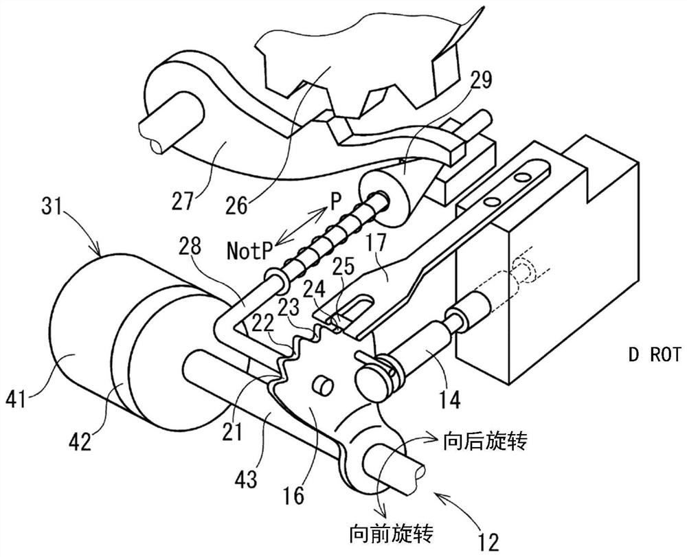
[0034] refer to figure 2 The range switching mechanism 12 is described. The range switching mechanism 12 includes a detent plate 16 and a detent spring 17 . The stop plate 16 changes the valve position of the gear switching valve 14 of the transmission hydraulic circuit depending on its rotational position. The range is switched according to the valve position of the range switching valve 14 . A plurality of recesses 21 to 24 corresponding to the respective gear positions are formed on the outer edge of the stopper plate 16 .
[0035] The stopper spring 17 is pressed to the stopper plate 16 by the pressing force of the stopper spring 17 . The locking portion 25 of the stopper spring 17 l...
no. 2 example
[0117] In the second embodiment, as Figure 11 As shown, the valley position learner 72 of the ECU 71 knows the partial valley positions of all the recesses 21 to 24 . The aforementioned “portion” means, for example, the recessed portion 21 and the recessed portion 23 . The valley position acquirer 72 acquires a specific pair of valley positions, that is, the P valley position and the N valley position.
[0118] The validity determiner 73 determines the validity of both the P valley position and the N valley position which are partial valley positions. More specifically, when the difference between the P valley position and the N valley position learned by the valley position acquirer 72 is within a predetermined normal range from ΔθPNL to ΔθPNH, the validity determiner 73 affirmatively determines the validity and validity of the P valley position. The validity of the N valley position, where the predetermined normal range of ΔθPNL to ΔθPNH is the design value of the rotatio...
no. 3 example
[0130] In the third embodiment, such as Figure 13 As shown, the valley position learner 82 of the ECU 81 knows the partial valley positions in all the recesses 21 to 24 . The “portion” mentioned above means, for example, the recessed portion 22 . The specific valley position learned by the valley position learner 82 is the R valley position.
[0131] The ECU 81 includes a peak point position learner 84 . The peak point position knower 84 knows, as the peak point position, the output shaft rotation angle θo when the locking portion 25 is positioned at the peak point between the two concave portions based on the detection value of the angle detector 61 . More specifically, when the output shaft rotation number No becomes equal to or greater than a predetermined value N2 during shift switching (see Figure 14 ), the peak point position acquirer 84 determines that the locking portion 25 has relatively moved to the peak point between the two recesses, and obtains the output sha...
PUM
 Abstract
Description
Claims
Application Information
 - R&D
- Intellectual Property
- Life Sciences
- Materials
- Tech Scout
- Unparalleled Data Quality
- Higher Quality Content
- 60% Fewer Hallucinations
Browse by: Latest US Patents, China's latest patents, Technical Efficacy Thesaurus, Application Domain, Technology Topic, Popular Technical Reports.
© 2025 PatSnap. All rights reserved.Legal|Privacy policy|Modern Slavery Act Transparency Statement|Sitemap|About US| Contact US: help@patsnap.com


