Al technical title is built by PatSnap Al team. It summarizes the technical point description of the patent document.
An optical lens, optical technology, used in optics, optical components, instruments, etc., can solve the problem of increasing the diameter of the lens, and achieve the effect of small CRA
Active Publication Date: 2020-10-27
NINGBO SUNNY AUTOMOTIVE OPTECH
View PDF5 Cites 4 Cited by
Summary
Abstract
Description
Claims
Application Information
AI Technical Summary
This helps you quickly interpret patents by identifying the three key elements:
Problems solved by technology
Method used
Benefits of technology
Problems solved by technology
[0005] At the same time, in the case of some special applications, such as the requirements for the night-time use effect of the vehicle lens, it is necessary to increase the light aperture of the lens to improve the night effect, which will also lead to an increase in the aperture of the lens
Method used
Image
Click on the blue label to locate the original text in one second.
Reading with bidirectional positioning of images and text.
Examples
Embodiment 1
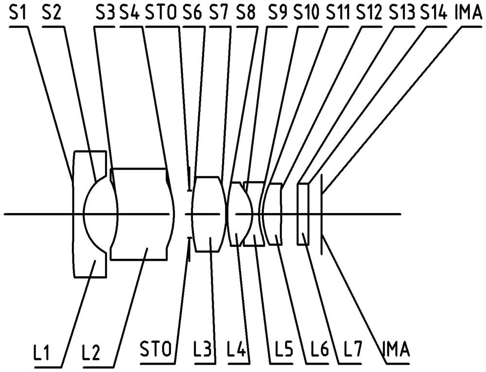
[0072] Refer to the following figure 1 An optical lens according to Embodiment 1 of the present application is described. figure 1 A schematic structural diagram of the optical lens according to Embodiment 1 of the present application is shown.
[0073] like figure 1 As shown, the optical lens sequentially includes a first lens L1 , a second lens L2 , a third lens L3 , a fourth lens L4 , a fifth lens L5 and a sixth lens L6 along the optical axis from the object side to the imaging side.
[0074] The first lens L1 is a meniscus lens with negative refractive power, the object side S1 is convex, and the image side S2 is concave.
[0075] The second lens L2 is a meniscus lens with positive refractive power, the object side S3 is concave, and the image side S4 is convex.
[0076] The third lens L3 is a biconvex lens with positive refractive power, and its object side S6 and image side S7 are both convex.
[0077] The fourth lens L4 is a biconvex lens with positive refractive po...
Embodiment 2
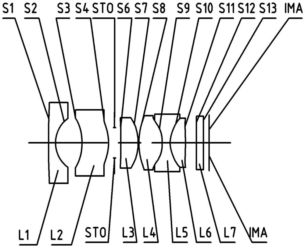
[0096] Refer to the following figure 2 An optical lens according to Embodiment 2 of the present application is described. In this embodiment and the following embodiments, for the sake of brevity, descriptions similar to those in Embodiment 1 will be omitted. figure 2 A schematic structural view of the optical lens according to Embodiment 2 of the present application is shown.
[0097] like figure 2 As shown, the optical lens sequentially includes a first lens L1 , a second lens L2 , a third lens L3 , a fourth lens L4 , a fifth lens L5 and a sixth lens L6 along the optical axis from the object side to the imaging side.
[0098] The first lens L1 is a meniscus lens with negative refractive power, the object side S1 is convex, and the image side S2 is concave.
[0099] The second lens L2 is a meniscus lens with positive refractive power, the object side S3 is concave, and the image side S4 is convex.
[0100] The third lens L3 is a biconvex lens with positive refractive p...
PUM
Abstract
An optical lens and imaging equipment including the optical lens are disclosed. The optical lens can sequentially comprise a first lens, a second lens, a third lens, a fourth lens, a fifth lens and asixth lens from the object side to the image side along the optical axis. The first lens can have negative focal power, the object side surface of the first lens is a convex surface, and the image side surface of the first lens is a concave surface; the second lens can have positive focal power, the object side surface of the second lens is a concave surface, and the image side surface is a convexsurface; the third lens can have positive focal power, and the object side surface and the image side surface of the third lens are convex surfaces; the fourth lens can have positive focal power, andthe object side surface and the image side surface of the fourth lens are convex surfaces; the fifth lens can have negative focal power, and the object side surface and the image side surface of thefifth lens are concave surfaces; and the sixth lens can have positive focal power, and the object side surface and the image side surface of the sixth lens are convex surfaces. According to the optical lens provided by the invention, at least one of the beneficial effects of high resolution, miniaturization, small front-end aperture, large aperture, small CRA, low cost, long rear focal length andthe like can be realized.
Description
technical field [0001] The present application relates to an optical lens and an imaging device including the optical lens, more particularly, the present application relates to an optical lens including six lenses and an imaging device. Background technique [0002] With the development of science, more and more fields need to use optical lenses as "eyes", such as vehicle, monitoring, projection, industrial fields, etc. [0003] With the growth of demand and the development of technology, the performance requirements of optical lenses are also getting higher and higher, especially the pixel requirements of optical lenses are very high, and the size of chips is also increased accordingly, resulting in the The size has also increased, and the cost has increased. [0004] For some applications with limited installation positions, such as optical lenses for vehicle applications, because they need to be installed in the car, the installation position is limited, such as the inn...
Claims
Application Information
Patent Timeline
Application Date:The date an application was filed.
Publication Date:The date a patent or application was officially published.
First Publication Date:The earliest publication date of a patent with the same application number.
Issue Date:Publication date of the patent grant document.
PCT Entry Date:The Entry date of PCT National Phase.
Estimated Expiry Date:The statutory expiry date of a patent right according to the Patent Law, and it is the longest term of protection that the patent right can achieve without the termination of the patent right due to other reasons(Term extension factor has been taken into account ).
Invalid Date:Actual expiry date is based on effective date or publication date of legal transaction data of invalid patent.