
Injection-tube-free thin film vapor chamber for portable electronic devices and manufacturing method thereof

A technology for electronic equipment and a manufacturing method, which is applied to structural parts of electrical equipment, portable housings, lighting and heating equipment, etc., can solve the problems of broken injection pipes, increased product defect rate, and difficulty in combining injection pipes.

Inactive Publication Date: 2020-10-27
POLAR&CO INC
View PDF1 Cites 0 Cited by
  • Summary
  • Abstract
  • Description
  • Claims
  • Application Information

AI Technical Summary

Problems solved by technology

[0009] However, in the existing patents, there are still problems with the traditional vapor chamber: the injection tube is injected with the working fluid through the injection tube and the injection tube is damaged during sealing, which causes the defect rate of the product to increase, and the injection tube when combined with the electronic product Problems with tube breakage or problems with difficult bonding due to the shape of the injection tube

Method used


Image

  • Injection-tube-free thin film vapor chamber for portable electronic devices and manufacturing method thereof
  • Injection-tube-free thin film vapor chamber for portable electronic devices and manufacturing method thereof
  • Injection-tube-free thin film vapor chamber for portable electronic devices and manufacturing method thereof

Examples


Embodiment Construction

[0040] Hereinafter, specific embodiments for carrying out the present invention will be described with reference to the drawings. The embodiments of the present invention are intended to illustrate an invention, so the scope of rights is not limited to the exemplary embodiments, and the illustrated drawings only expand and illustrate the core content of the invention for the clarity of the invention, and omit the subsidiary parts, so it cannot be limited Explain with the accompanying drawings.

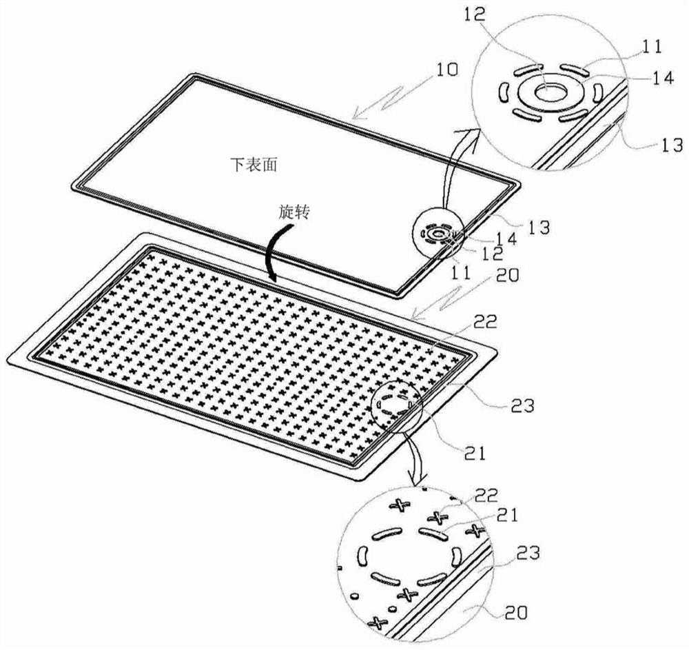
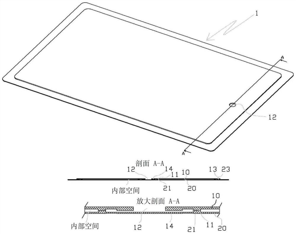
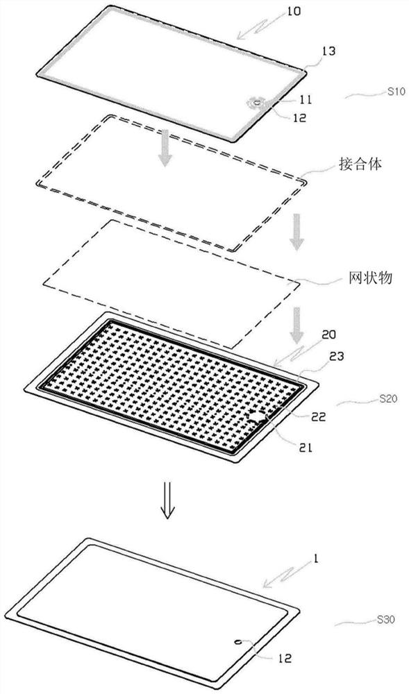
[0041] According to the vapor chamber (VaporChamber) provided in the portable electronic device provided by the present invention, it is characterized in that it includes: a lower plate 20, which is formed into a metal plate shape, and a plurality of protrusions are formed on its upper surface 22, and the upper surface of one side is formed with a plurality of first projections 21 spaced apart and protruding at predetermined intervals, and a first engaging body 23 is formed from the oute...


PUM


Abstract

The invention relates to an injection-tube-free thin film vapor chamber for portable electronic devices and a manufacturing method thereof. The thin film vapor chamber comprises a lower plate, whereinmultiple protrusions are formed on the upper surface of the lower plate, multiple first protrusions, which are separated from each other in a predetermined space and protrude, are formed on the uppersurface of one side of the lower plate, and a first joint body, which protrudes from the outer edge to the inner side at a predetermined space along the edge shape, is formed; and an upper plate, which is provided with a protruded second joint body that is jointed to the upper side of the lower plate, wherein second protrusions corresponding to the first protrusions are formed. An injection portfor injecting a work fluid is formed in the inner side of the second protrusions. When the lower plate bends and contacts with the injection port, a segment gap is formed when the sealed injection port protrudes downwards; through a vacuum injection body, the vacuum injection body is tightly adhered on the injection port of the upper plate, the upper plate and the lower plate are jointed, an internal space formed between the upper plate and the lower plate is in a vacuum state, and the work fluid is injected into the internal space.

Description

technical field [0001] The present invention relates to a thin-film vapor chamber for portable electronic equipment without an injection tube and a manufacturing method thereof, and more specifically, to the following thin-film vapor chamber for portable electronic equipment and a manufacturing method thereof, wherein the portable electronic equipment The inner space of the thin film vapor chamber for equipment is formed in a vacuum state, and the injection port for injecting the working fluid is formed in a flat surface. Therefore, the inconvenience of providing a cooling device inside the portable electronic device can be eliminated, a vacuum state can be quickly formed in the internal space, and a large amount of working fluid can be injected in a short time. Since the injection port is formed on a flat surface, it is possible to prevent breakage of the vapor chamber and manufacturing defects at the time of forming a vacuum or injecting a working fluid and sealing. Backgr...

Claims


Application Information

Patent Timeline
Patent Type & Authority Applications(China)
IPC IPC(8): H05K7/20G06F1/20
CPCG06F1/203H05K7/2029H05K7/20327F28D15/0233H05K7/20336H05K5/0086H05K7/2039
Inventor 李基雨金宗善金相景崔京龙
Owner POLAR&CO INC
Learn More