
Descent control device with controllable speed

A technology of slow descent device and speed, applied in life-saving equipment, building rescue and other directions, can solve the problems of safety hazards of falling, affecting the efficiency of escape, misoperation, etc., to improve reliability and reduce the dependence of reliability. Effect

Pending Publication Date: 2020-10-30
HUBEI UNIV OF SCI & TECH
View PDF0 Cites 1 Cited by
  • Summary
  • Abstract
  • Description
  • Claims
  • Application Information

AI Technical Summary

Problems solved by technology

Most of the existing methods are through the damping control of the slow-down rope or slow-down belt, that is, the way of friction. The descending speed needs to be preset, and the descending speed needs to be controlled in real time according to the situation of the fire scene. The actual situation of the escaping personnel comprehensively considers the safety of slow descent and the efficiency of escape. In an emergency, it is often not very reasonable to preset the speed before escaping, and it will also affect the efficiency of escape. Misjudgment, and the fire scene may be located under the floor where the escaped personnel are, which also requires a faster descent speed in the case of a greater fire hazard, and the descent speed will also change significantly with the change of the descent height. Controlling the speed at any time has a great potential safety hazard for falling injuries. All the above situations reflect the necessity of the speed control of the life-saving slow-descent device.

Method used


Image

  • Descent control device with controllable speed
  • Descent control device with controllable speed
  • Descent control device with controllable speed

Examples


Embodiment Construction

[0029] The following are specific embodiments of the present invention and in conjunction with the accompanying drawings, the technical solutions of the present invention are further described, but the present invention is not limited to these embodiments.

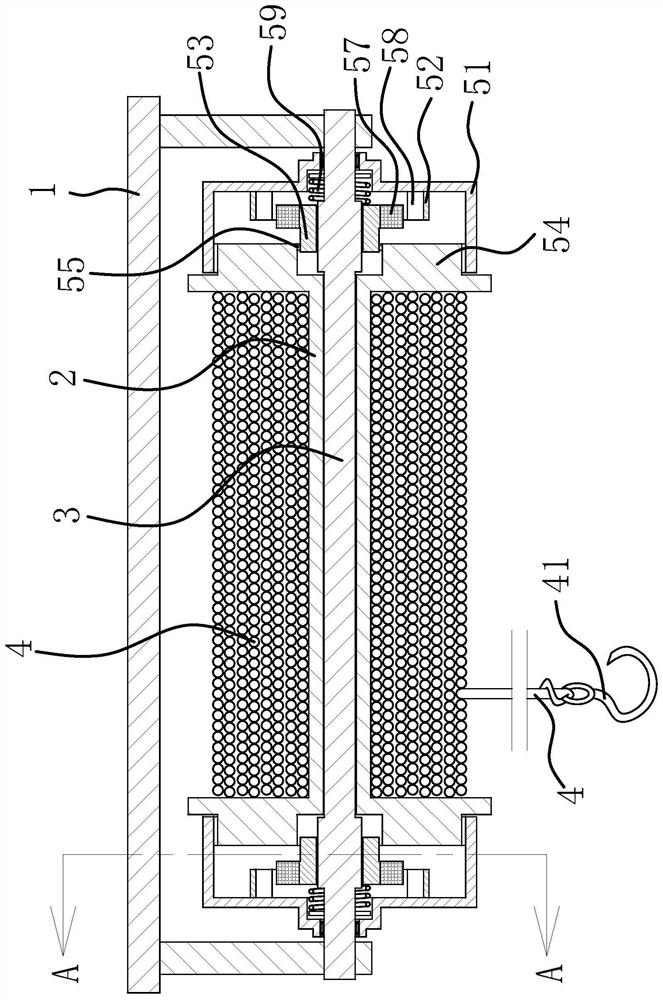
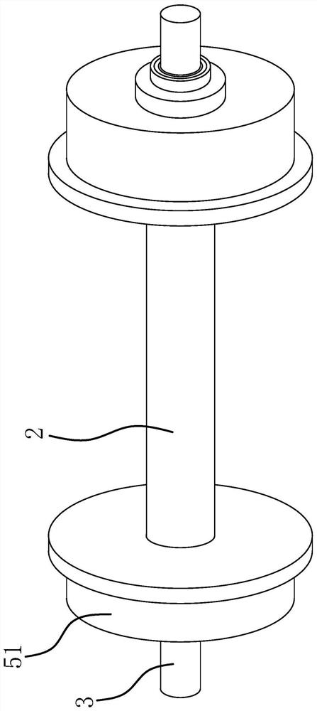
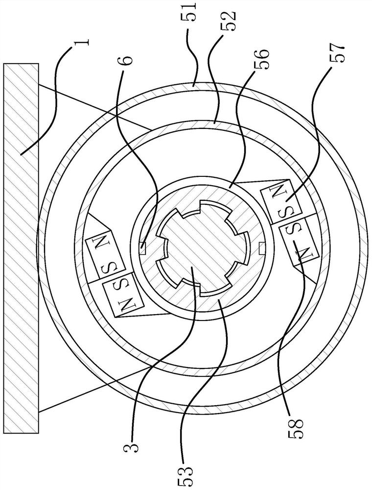
[0030] Such as Figure 1 to Figure 5 As shown, it includes a mounting plate 1, a retracting drum 2, a mounting shaft 3 and a slow-down rope 4, the mounting shaft 3 is fixedly arranged on the mounting plate 1, the retracting drum 2 is rotatably connected to the mounting shaft 3, and one end of the slow-down rope 4 Fixed on the winding drum 2, the other end of the slow down rope 4 is provided with a locking hook 41, and a magnetic damping mechanism is arranged between the two ends of the installation shaft 3 and the winding drum 2 respectively, and the magnetic damping mechanism includes a magnetic damping mechanism fixed on the winding drum. The drum 51 on the drum 2 is rotatably connected to the mounting shaft 3, and a rot...


PUM


Abstract

The invention provides a descent control device with controllable speed, and belongs to the technical field of fire-fighting and life-saving tools. The descent control device with controllable speed comprises a mounting plate, a winding drum, a mounting shaft and a descent control rope, wherein the mounting shaft is fixedly arranged on the mounting plate; the winding drum is rotatably connected tothe mounting shaft; one end of the descent control rope is fixed to the winding drum; a magnetic force damping mechanism is arranged between each end of the mounting shaft and the winding drum, and comprises an electromagnetic component on which a coil wire is wound; an electric current control switch is arranged at one end, provided with a lock hook, of the descend control rope; the two coil wires are in parallel connection, and then are connected to the electric current control switch; and an electrified wire between the electric current control switch and each coil wire loosely penetratesinto a perforating hole. The descent control device with controllable speed has the advantages of high reliability and the like.

Description

technical field [0001] The invention belongs to the technical field of fire-fighting and life-saving tools, and relates to a speed-controllable slow descender. Background technique [0002] The life-saving descending device is a common fire-fighting and life-saving equipment. In the event of a fire, escape personnel located in high buildings can escape the fire scene along the outer wall of the building through the life-saving descending device. Most of the existing methods are through the damping control of the slow-down rope or slow-down belt, that is, the way of friction. The descending speed needs to be preset, and the descending speed needs to be controlled in real time according to the situation of the fire scene. The actual situation of the escaping personnel comprehensively considers the safety of slow descent and the efficiency of escape. In an emergency, it is often not very reasonable to preset the speed before escaping, and it will also affect the efficiency of e...

Claims


Application Information

Patent Timeline
Patent Type & Authority Applications(China)
IPC IPC(8): A62B1/06A62B1/18
CPCA62B1/06A62B1/18
Inventor 孙刘萍魏学胜
Owner HUBEI UNIV OF SCI & TECH
Learn More