
A beam-lifting and bending device for a copper hot pot basin

A bending device, hot pot technology, applied in stripping devices, metal processing equipment, manufacturing tools, etc., can solve the problems of cumbersome operation process, low work efficiency, manpower consumption, etc., and achieve simple operation, improve work efficiency, and save manpower. Effect

Active Publication Date: 2022-07-08
何海丹
View PDF6 Cites 0 Cited by
  • Summary
  • Abstract
  • Description
  • Claims
  • Application Information

AI Technical Summary

Problems solved by technology

[0006] In order to overcome the shortcomings of the above-mentioned method, which are cumbersome and manpower-intensive, need to be bent twice, and have low work efficiency, the technical problem to be solved by the present invention is to provide a simple operation that can save manpower and improve work Efficient copper chafing dish basin lifting beam bending device

Method used


Image

  • A beam-lifting and bending device for a copper hot pot basin
  • A beam-lifting and bending device for a copper hot pot basin
  • A beam-lifting and bending device for a copper hot pot basin

Examples


Embodiment 1

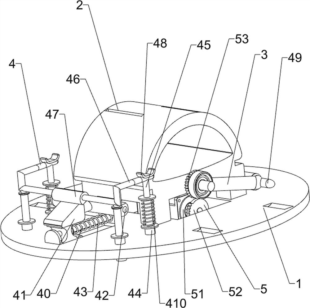
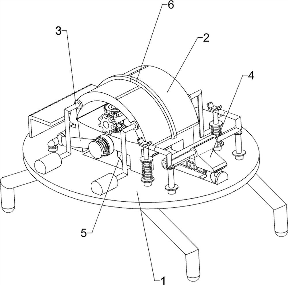
[0023] A beam-lifting and bending device for a copper hot pot basin, such as Figure 1-2 It includes a bottom plate 1, a bending seat 2 and a U-shaped pressing rod 3, the top of the bottom plate 1 is connected with a bending seat 2, and a U-shaped pressing rod 3 is rotatably connected to the bending seat 2, and also includes a transmission mechanism 4 and Drive mechanism 5, a transmission mechanism 4 and a drive mechanism 5 are arranged on the bottom plate 1.

[0024] The transmission mechanism 4 includes a wedge-shaped seat 41, a push rod 42, a guide rod 40, a return spring 43, a sleeve 44, a sliding rod 45, a connecting rod 46, an inclined rod 47, a card seat 48, a convex rod 49 and a compression spring 410, the bottom plate 1 A guide rod 40 is connected to the right side of the top, a wedge seat 41 is slidably connected to the guide rod 40, a return spring 43 is connected between the wedge seat 41 and the guide rod 40, a push rod 42 is connected to the left side of the wedg...

Embodiment 2

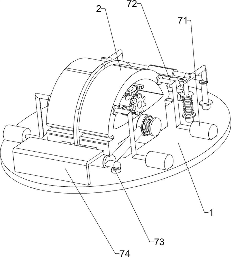
[0028] On the basis of Example 1, as image 3 As shown, it also includes a discharge mechanism 6, and the discharge mechanism 6 includes a mounting seat 61, a second bevel gear 62, a first bevel gear 60, a dial 63, a shaft seat 64, a transmission gear 65, an L-shaped rack 66, The arc-shaped plate 67, the elastic member 68 and the torsion spring 69, the inner bottom of the bending seat 2 is connected with a mounting seat 61, and the front and rear sides of the mounting seat 61 are rotatably connected with the first bevel gear 60 and the second bevel gear 62. A bevel gear 60 is located on the lower side of the mounting seat 61, the rear first bevel gear 60 is located on the upper side of the mounting seat 61, the first bevel gear 60 and the second bevel gear 62 on the same side mesh with each other, and the second bevel gear 62 is connected with a dial Wheel 63, a shaft seat 64 is connected to the front and rear sides of the inner top of the bending seat 2, and a transmission ge...


PUM


Abstract

The invention relates to a bending device, in particular to a lifting beam bending device for a copper hot pot basin. The technical problem to be solved by the present invention is how to design a beam-lifting and bending device for a copper hot pot basin which is easy to operate, saves manpower and improves work efficiency. In order to solve the above technical problems, the present invention provides such a lifting beam bending device for a copper hot pot basin, which includes: a bottom plate, the top of which is connected with a bending seat; a U-shaped pressing rod, which is rotatably connected to the bending seat; The transmission mechanism is arranged on the base plate; the drive mechanism is arranged on the base plate. The present invention bends the lifting beam through the coordinated operation of the transmission mechanism and the driving mechanism, so as to achieve the effect of bending the lifting beam.

Description

technical field [0001] The invention relates to a bending device, in particular to a lifting beam bending device for a copper hot pot basin. Background technique [0002] Hotpot, known as "Antique Soup" in ancient times, is named after the "gu-dong" sound when food is put into boiling water. It is a unique Chinese food with a long history and is suitable for all ages. According to research, there was hot pot during the Warring States Period, and people used clay pots as pots. The hot pot is usually produced by using a hot pot pot. When the hot pot pot is produced, the lifting beam is usually installed on the hot pot pot, and the lifting beam needs to be bent during the production. [0003] At present, the lifting beam is usually bent by manually inserting one side of the lifting beam on the bending equipment, and then operating the bending equipment to bend it. After bending, there is still a section of the lifting beam that is not bent. The folded side is inserted on the ...

Claims


Application Information

Patent Timeline
Patent Type & Authority Patents(China)
IPC IPC(8): B21D11/22B21D11/00B21D45/00
CPCB21D11/22B21D11/00B21D45/00
Inventor 何海丹
Owner 何海丹
Learn More