Automatic bending device for two ends of copper wire

A bending device and copper wire technology, which is applied in the field of automatic bending devices at both ends of copper wires, can solve the problems of cumbersome operation process, low work efficiency, and manpower consumption, so as to achieve simple operation, improve work efficiency, and save manpower consumption Effect

Active Publication Date: 2020-08-07
艾雷特环保科技宿迁有限公司
View PDF6 Cites 0 Cited by
  • Summary
  • Abstract
  • Description
  • Claims
  • Application Information

AI Technical Summary

Problems solved by technology

[0004] In order to overcome the cumbersome operation process of the above method, which is relatively labor-intensive, and can only be bent by a single piece during operation, and the shortcomings of low work efficiency, the technical problem is to provide a relatively simple operation process, which can save manpower and can effectively Automatic bending device at both ends of copper wire to improve work efficiency

Method used


Image

  • Automatic bending device for two ends of copper wire
  • Automatic bending device for two ends of copper wire
  • Automatic bending device for two ends of copper wire

Examples


Embodiment 1

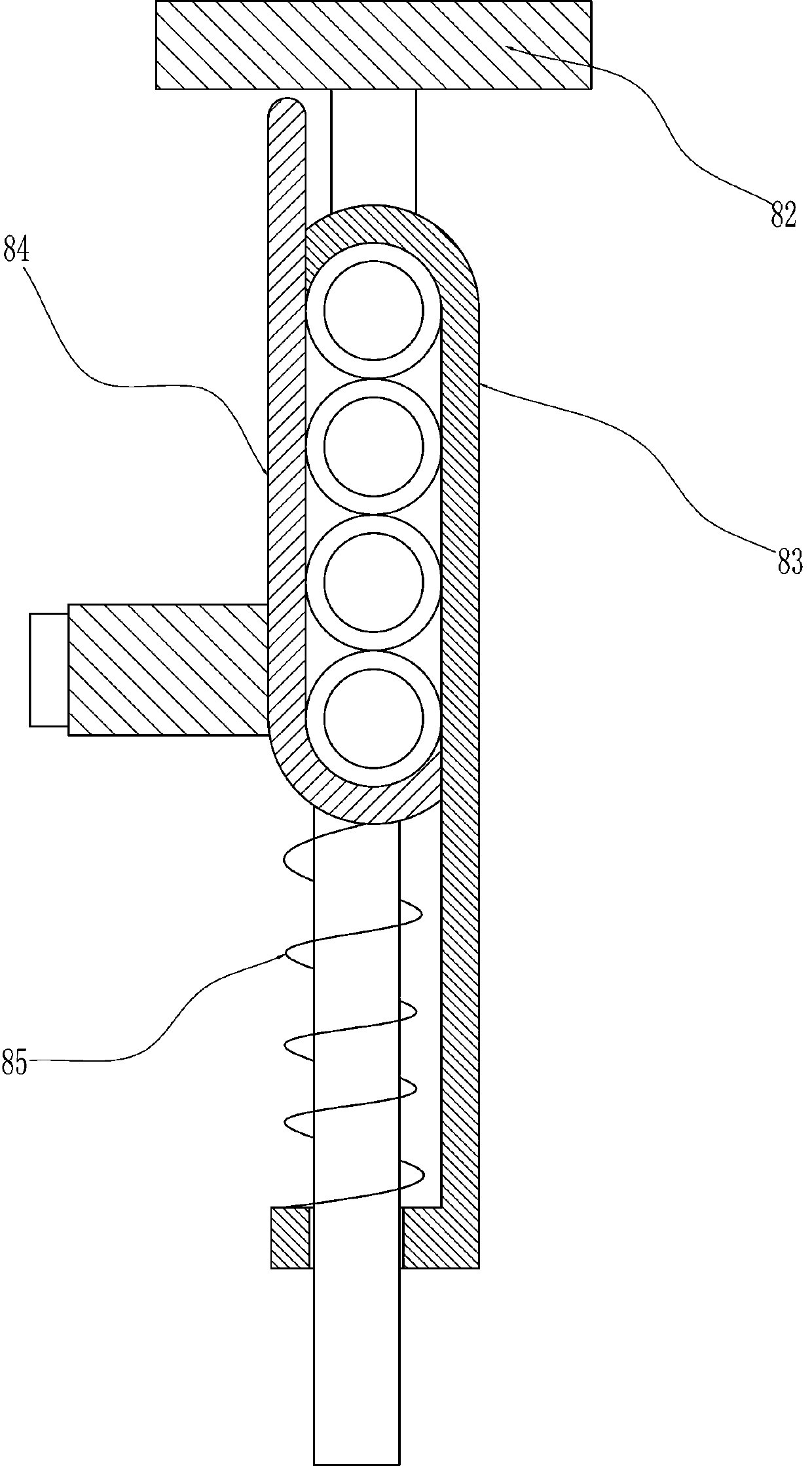
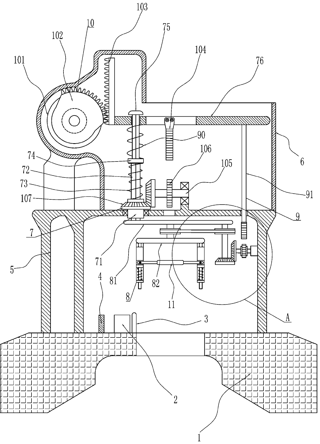
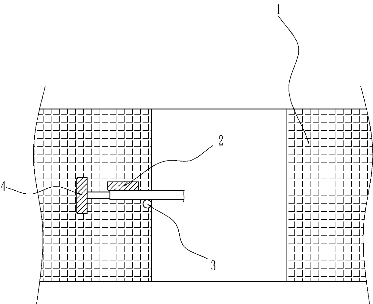
[0022] An automatic bending device at both ends of a copper wire, such as Figure 1-4 As shown, it includes a base 1, a first limiting plate 2, a second limiting plate 3, a torsion bar 4, a workbench 5 and an installation box 6, and the top of the base 1 is connected with the first limiting plate 2, the second limiting plate Plate 3 and torsion bar 4, the first limiting plate 2 is located at the rear side of the second limiting plate 3, the torsion bar 4 is located on the left side of the first limiting plate 2 and the second limiting plate 3, and the top of the base 1 is connected with Workbench 5, installation box 6 is installed on the top of workbench 5, and also includes moving assembly 7 and charging assembly 8, between workbench 5 and installation box 6, there is moving assembly 7, and moving assembly 7 is provided with charging assembly 8 .

[0023] The moving assembly 7 includes an inner diamond sleeve 71, a rhombus rod 72, a first return spring 73, an axle sleeve 74 ...

Embodiment 2

[0027] On the basis of Example 1, such as figure 1 As shown, a diamond-shaped guide rod 75 is also included, and the top of the bushing 74 is connected with a rhombus-shaped guide rod 75 , a sliding plate 76 is slidably matched with the diamond-shaped guide rod 75 , and there is a certain resistance between the sliding plate 76 and the diamond-shaped guide rod 75 .

[0028] When the slide plate 76 moves downward, the diamond-shaped guide rod 75 can play a guiding role.

[0029] Such as figure 1 and Figure 4 As shown, a rotating assembly 9 is also included, and the rotating assembly 9 includes a driving rack 91, a first rotating shaft 92, a one-way clutch 93, a driving gear 94, a second rotating shaft 95, a first bevel gear 96 and a compression spring 90, sliding The right side of the bottom of the plate 76 is connected with a driving rack 91, and the driving rack 91 is slidingly matched with the workbench 5. The inner right wall of the workbench 5 is rotatably connected wit...

Embodiment 3

[0032] Such as figure 1 As shown, a drive assembly 10 is also included, and the drive assembly 10 includes a motor 101, a sector gear 102, a first spur rack 103, a second spur rack 104, a mounting shaft 105, a cylindrical gear 106 and a second bevel gear 107, Mounting box 6 top left side is equipped with motor 101, is connected with sector gear 102 on the output shaft of motor 101, is connected with the first spur rack 103 that can mesh with sector gear 102 on the left side of slide plate 76, is connected with on slide plate 76 The second spur rack 104, the top of the workbench 5 is rotatably connected with the mounting shaft 105, the mounting shaft 105 is connected with a cylindrical gear 106, the cylindrical gear 106 will mesh with the second spur rack 104, and the end of the mounting shaft 105 is connected to the inner diamond sleeve Both the pipes 71 are connected with second bevel gears 107, and the two second bevel gears 107 mesh with each other.

[0033] The starter mo...


PUM


Abstract

The invention relates to a bending device, in particular to an automatic bending device for the two ends of a copper wire. The automatic bending device for the two ends of the copper wire is simple inoperation process and capable of saving labor, and effectively improving the work efficiency. The automatic bending device for the two ends of the copper wire comprises a base, a workbench, a movingassembly and a feeding assembly, wherein the top of the base is connected with a first limiting plate and a second limiting plate and an twisting rod. The first limiting plate, the second limiting plate and the twisting rod are used for clamping the copper wire, the workbench is connected to the top of the base, an installation box is installed on the top of the workbench, the moving assembly is arranged between the workbench and the installation box, and the feeding assembly is arranged on the moving assembly and used for holding the copper wire. According to the automatic bending device forthe two ends of the copper wire, the first limiting plate, the second limiting plate, the twisting rod and the moving assembly cooperate to operate together with the feeding assembly so as to bend thecopper wire, and then the effect of bending the copper wire is achieved.

Description

technical field [0001] The invention relates to a bending device, in particular to an automatic bending device for two ends of a copper wire. Background technique [0002] Copper wire can be used to make wires. It has good electrical conductivity and is widely used in the manufacture of wires, cables, brushes, etc.; it has good thermal conductivity and is often used to manufacture magnetic instruments and instruments that must prevent magnetic interference, such as electric meters and aviation instruments; it has excellent plasticity, and now there are some copper The manufacturer of the wire will bend the copper wire before leaving the factory, and the bent copper wire can be directly connected to the electric meter or air switch. [0003] At present, the way to bend the copper wire is usually to manually clamp the copper wire on the bending part, and then pull the unclamped part of the copper wire to bend backwards, so as to achieve the effect of bending the copper wire. ...

Claims


Application Information

Patent Timeline
IPC IPC(8): B21F1/00
CPCB21F1/00
Inventor 李燕红
Owner 艾雷特环保科技宿迁有限公司
Why Eureka
Try Eureka