Shaping equipment

An equipment and plate technology, applied in the field of plastic forming equipment that can elastically reshape plates, can solve the problems of lowering the overall yield, lack of plate elasticity, damage to the plate by the contact area, etc., to increase the convenience of operation, improve the quality rate effect

Active Publication Date: 2020-05-01
JABIL CIRCUIT SINGAPOREPTE
View PDF17 Cites 0 Cited by
  • Summary
  • Abstract
  • Description
  • Claims
  • Application Information

AI Technical Summary

Problems solved by technology

[0004] However, the pressing block of the above-mentioned conventional shaping tool is used to shape the panel in a single fixed shape. If it is necessary to press and bond panels of different shapes, a corresponding pressing block must be installed separately. This not only lacks the elasticity of panel shaping, but also In the conventional pressing process, due to the large contact area between the pressing block and the board, it is easy to rub and damage the board, reducing the overall yield

Method used


Image

  • Shaping equipment
  • Shaping equipment
  • Shaping equipment

Examples


Embodiment Construction

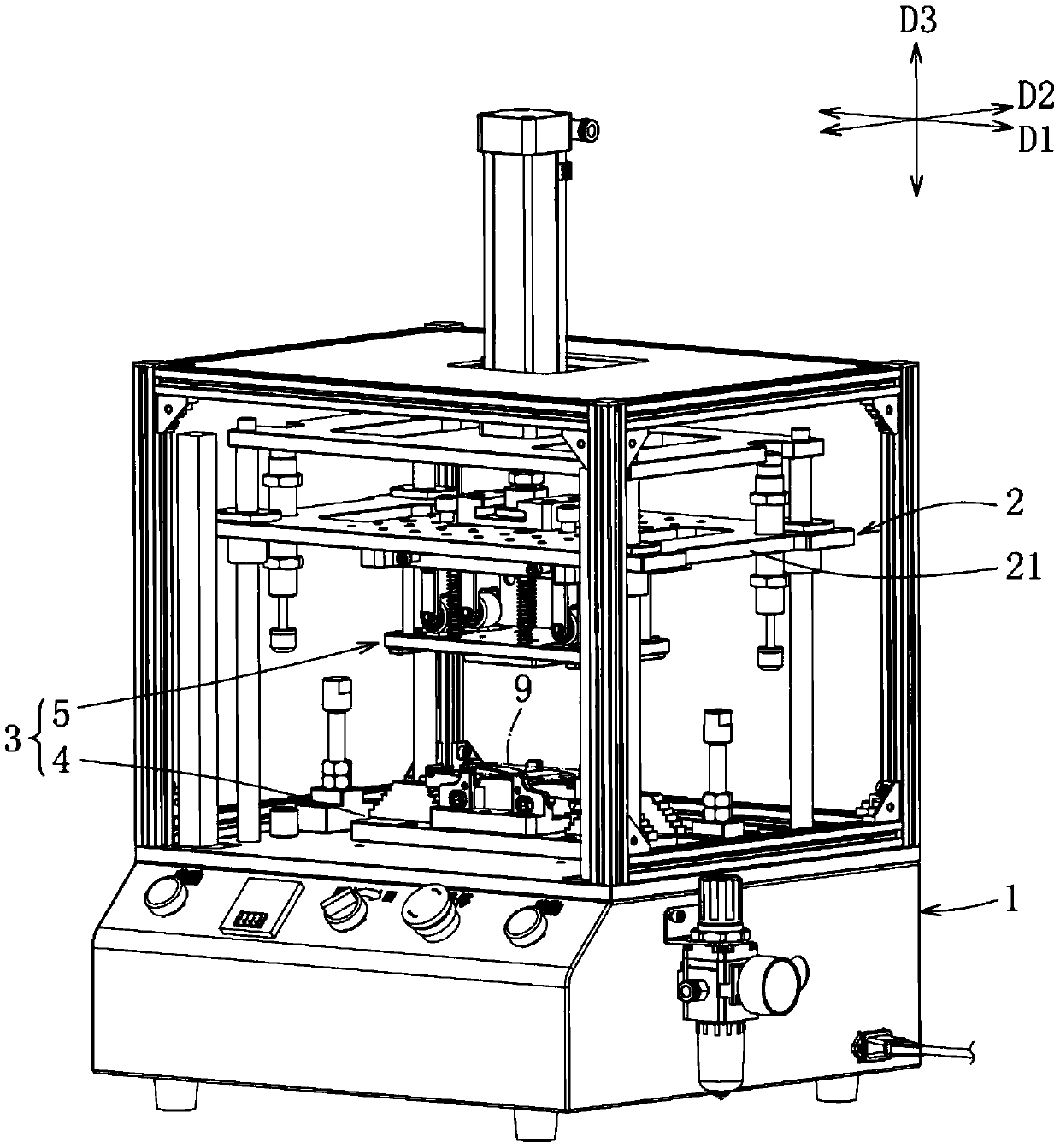
[0038] refer to figure 1 , an embodiment of the molding equipment of the present invention for molding a plate 9 , the molding equipment includes a carrier 1 , a driving device 2 and a pressing device 3 . In this embodiment, the plate 9 is, for example, a mobile phone case, but not limited to the mobile phone case, as long as the plate 9 is made of ductile material, it can be processed by shaping equipment.

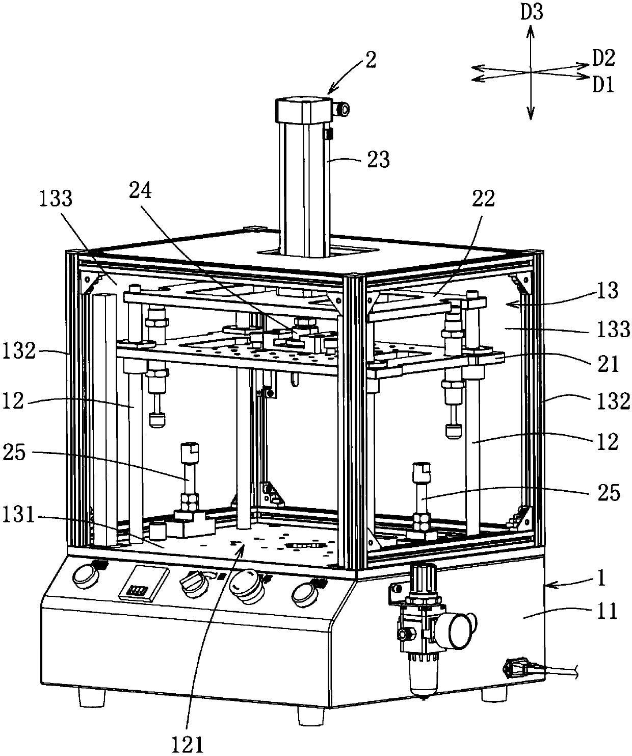
[0039] refer to figure 1 and figure 2 The stage 1 includes a control base 11 , four inner brackets 12 surrounding the top surface of the control base 11 for the drive device 2 to install, and a shielding unit 13 surrounding the inner bracket 12 and forming a forward opening 131 . The inner frame 12 jointly defines a working area 121 for the driving device 2 and the pressing device 3 to perform mechanical actions. In addition, the shielding unit 13 has four outer frames 132 surrounding the inner frame 12 and a plurality of shields 133 connected to the outer frames 132 ...


PUM


Abstract

Shaping equipment comprises a carrying table, a driving device and a press-fitting device. The driving device comprises a lifting table capable of moving vertically relative to the carrying table. Thepress-fitting device comprises a lower press-fitting unit and an upper press-fitting unit. The lower press-fitting unit is provided with a lower positioning plate for arranging the carrying table, aseat for arranging the lower positioning plate, at least one swing arm piece, at least one bearing piece and reset elastic pieces, wherein the swing arm pieces are used for carrying a plate and is arranged on the seat in a pivoted mode, the other ends of the swing arm pieces can move vertically, the bearing pieces are used for bracketing the swing arm pieces, one end of each resect elastic piece is connected with the seat, and the other end of each reset elastic piece is connected with the corresponding swing arm piece. The upper press-fitting unit is provided with an upper positioning plate used for arranging the lifting table, a plurality of guide connecting rods, a pressing plate and pressing pieces, wherein one side of each guide connection rod penetrates through the upper positioningplate, the pressing plate is connected with the other sides of the guide connecting rods and presses and abuts against the plate along with descending of the lifting table, at least one side of each pressing piece is connected with the upper positioning plate, and the pressing pieces can be matched with the swing arm pieces. When the pressing plate and the pressing pieces are pushed by the liftingtable to press and abut against the plate, the pressing pieces can be further pushed by the upper positioning plate to drive the swing arm pieces to pivot towards the bearing pieces and make corresponding parts of the plate be bent.

Description

technical field [0001] The invention relates to a shaping device, in particular to a shaping device capable of elastically shaping a plate. Background technique [0002] The existing plate shaping uses a shaping block and a pressing block as a shaping mold. By setting the plate to be shaped on the workbench, a driving device is used to push the pressing block and exert pressure together with the shaping block. For the board, such as a mobile phone casing. [0003] For example, Chinese Patent Publication No. CN106142522A discloses a shape-setting tool for plastic parts. The shape-setting tool mainly includes a workbench, shaping blocks, multiple guide rods and a hydraulic control system. block, moving plate and fixed plate, and the pressing block exerts pressure on the plate placed on the shaping block through the hydraulic control system to achieve the purpose of shaping. [0004] However, the pressing block of the above-mentioned conventional shaping tool is used to shape...

Claims


Application Information

Patent Timeline
IPC IPC(8): B29C53/04
CPCB29C53/04
Inventor 吴玉农
Owner JABIL CIRCUIT SINGAPOREPTE
Why Eureka
Try Eureka