Rapid heat dissipation cutting machine

A cutting machine, fast technology, used in metal processing machinery parts, maintenance and safety accessories, metal processing equipment, etc., can solve the problems of inability to quickly cool down the spindle and bearings, poor heat absorption effect, etc.

Active Publication Date: 2020-10-30
QUANZHOU HAIENDE ELECTROMECHANICAL TECH DEV
View PDF4 Cites 2 Cited by
  • Summary
  • Abstract
  • Description
  • Claims
  • Application Information

AI Technical Summary

Problems solved by technology

However, in the existing cooling method, since the coolant can only circulate in the spindle box and cannot directly contact

Method used


Image

  • Rapid heat dissipation cutting machine
  • Rapid heat dissipation cutting machine
  • Rapid heat dissipation cutting machine

Examples


Embodiment Construction

[0045] In order to further explain the technical solution of the present invention, the present invention will be described in detail below through specific examples.

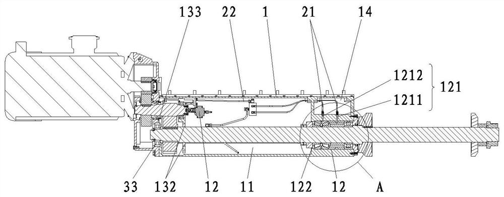
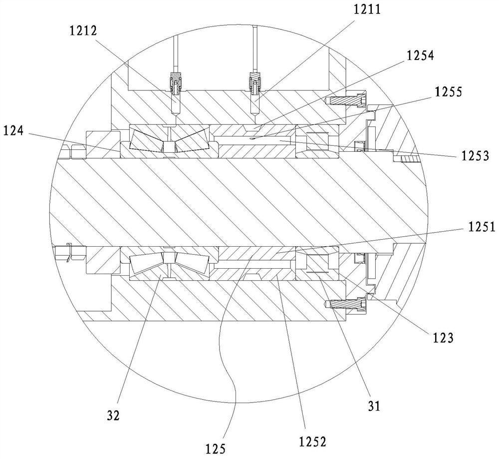
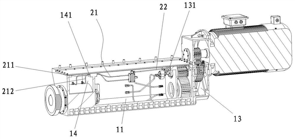
[0046] Such as Figure 1-3 As shown, a cutting machine with rapid heat dissipation includes a main body of the cutting machine, and the main body of the cutting machine includes a headstock 1; wherein, the headstock 1 includes a liquid storage chamber 11 for storing cooling liquid, and a first cooling chamber for cooling the bearing at one end of the main shaft 12, and the second cooling cavity 13 for cooling the bearing at the other end of the main shaft.

[0047] After adopting the above structure, during operation, the liquid storage chamber 11 can be used to store cooling liquid, and the cooling liquid in the liquid storage chamber 11 can contact the main shaft to absorb heat and cool the main shaft. In addition, the spindle box 1 is also provided with a first cooling cavity 12 and a second cooling cavity ...


PUM


Abstract

The invention discloses a rapid heat dissipation cutting machine. The cutting machine comprises a cutting machine main body. The cutting machine main body comprises a main shaft box, wherein the mainshaft box comprises a liquid storage cavity for storing a cooling liquid, a first cooling cavity for cooling a bearing of one end of the main shaft, and a second cooling cavity for cooling a bearing of the other end of the main shaft. After the structure is adopted, the cooling liquid in the liquid storage cavity can be in contact with the main shaft to cool the main shaft. In addition, the firstcooling cavity and the second cooling cavity are used for mounting and fixing the bearings of the main shaft. The cooling liquid in the liquid storage cavity can be conveyed into the first cooling cavity and the second cooling cavity and is in contact with the bearings to absorb heat, so that the bearings are subjected to heat dissipation and cooling treatment. Finally, the cooling liquids withinthe first cooling cavity and the second cooling cavity flow back into the liquid storage cavity. Compared with the prior art, the cooling liquid of the cutting machine circularly flows in the main shaft box and makes contact with the main shaft and the bearings so as to perform rapidly heat absorption and cooling on the main shaft and the bearings, and therefore cooling and heat dissipation of thecutting machine are accelerated.

Description

technical field [0001] The invention relates to the field of cutting machines, in particular to a cutting machine with rapid heat dissipation. Background technique [0002] The cutting machine is mainly used for cutting and separating the plates during the machining process. Existing cutting machines are mainly provided with a rotatably connected main shaft in the main shaft box, on which a cutting saw blade is installed, and the main shaft is driven to rotate by a driving device, thereby driving the cutting saw blade to cut. During the cutting process, due to the high-speed rotation of the main shaft, the temperature of the main shaft and bearings will be too high, which will cause the main shaft and bearings to expand and affect the cutting accuracy. [0003] In order to solve the above-mentioned problem of excessively high temperature of the main shaft and bearings, most of the existing cutting machines open a cooling liquid flow groove on the side wall of the main shaft...

Claims


Application Information

Patent Timeline
IPC IPC(8): B23Q11/12
CPCB23Q11/12
Inventor 林智敏洪培英丁革新吴宝霖林榕栋黄嘉鸿
Owner QUANZHOU HAIENDE ELECTROMECHANICAL TECH DEV
Why Eureka
Try Eureka