Cutting machine with efficient heat dissipation function

A cutting machine, high-efficiency technology, applied in the direction of mechanical equipment, metal sawing equipment, sawing machine accessories, etc., can solve the problems of ignoring bearing cooling, easy expansion and deformation, high temperature of main shaft and bearing, etc.

Pending Publication Date: 2020-10-30
QUANZHOU HAIENDE ELECTROMECHANICAL TECH DEV
View PDF8 Cites 4 Cited by
  • Summary
  • Abstract
  • Description
  • Claims
  • Application Information

AI Technical Summary

Problems solved by technology

[0003] However, during the cutting process, due to the high-speed rotation of the main shaft, the temperature of the main shaft and bearings will be too high, which will cause the main shaft and bearings to expand and affect the cutting accuracy.
For this reason, a method of using coolant to dissipate heat inside the cutting machine is designed. Although the use of coolant can effectively reduce the working temperature of the spindle, it ignores the cooling of the bearings. Since the bearings are mainly sealed and installed at the front and rear ends of the spindle, It is difficult for coolant to flow through the bearing to cool and dissipate it. The bearing is easy to expand and deform in a long-term high-temperature environment. In severe cases, the bearing may even be locked, resulting in damage to the spindle and motor.

Method used


Image

  • Cutting machine with efficient heat dissipation function
  • Cutting machine with efficient heat dissipation function
  • Cutting machine with efficient heat dissipation function

Examples


Embodiment Construction

[0097] In order to further explain the technical solution of the present invention, the present invention will be described in detail below through specific examples.

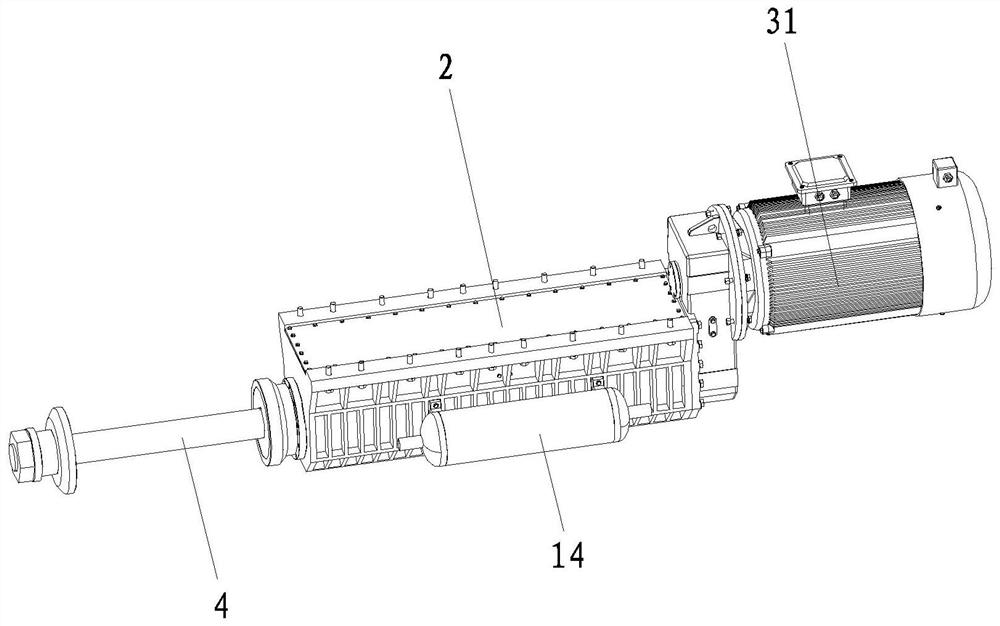
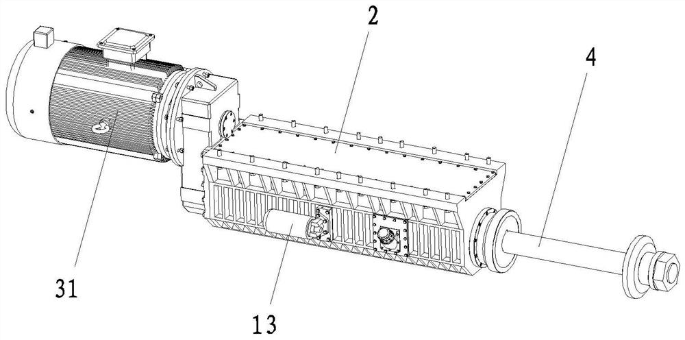
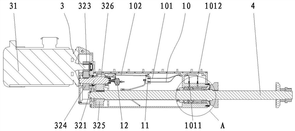
[0098] Such as Figure 1-7 As shown, a high-efficiency heat dissipation cutting machine includes a cutting machine main body; wherein, it also includes a heat dissipation device for cooling the main shaft 4 bearing of the cutting machine main body through flowing coolant. The heat dissipation device includes a cooling liquid delivery pipe for delivering cooling liquid to the heat-generating parts of the main body of the cutting machine; the cooling liquid delivery pipe includes more than two shunt pipes 10 corresponding to two or more heat-generating parts for cooling. The distribution pipe 10 is equipped with a valve (not shown) that matches the cooling liquid flow rate according to the heat generated by the heat-generating part. In this embodiment, the valve can be an adjustable solenoid valve.

[0099] Afte...


PUM


Abstract

The invention discloses a cutting machine with an efficient heat dissipation function. The cutting machine comprises a cutting machine main body, and further comprises a heat dissipation device used for dissipating heat of main shaft and bearings of the cutting machine main body through flowing cooling liquid, wherein the heat dissipation device comprises a cooling liquid conveying pipeline for conveying the cooling liquid to heating parts of the cutting machine main body; and the cooling liquid conveying pipeline comprises two or more flow dividing pipelines used for cooling two or more heating parts in a one-to-one correspondence mode, and the flow dividing pipelines are provided with valves used for matching the flow amount of the cooling liquid according to the calorific value of the heating parts. By the adoption of the structure, compared with the prior art, the cutting machine with the efficient heat dissipation function can fully cool the bearings and the main shaft, the heat dissipation speed is high, and the heat dissipation efficiency is high; and meanwhile, the cooling liquid circularly flows, so that the use amount of the cooling liquid is saved, meanwhile cooling liquid pollution and consumption are reduced, and the cooling cost is greatly saved.

Description

technical field [0001] The invention relates to the field of cutting machines, in particular to a high-efficiency heat dissipation cutting machine. Background technique [0002] The cutting machine is mainly used for cutting and separating the plates during the machining process. Existing cutting machines are mainly provided with a rotatably connected main shaft in the main shaft box, on which a cutting saw blade is installed, and the main shaft is driven to rotate by a driving device, thereby driving the cutting saw blade to cut. [0003] However, during the cutting process, due to the high-speed rotation of the main shaft, the temperature of the main shaft and the bearing will be too high, which will cause the main shaft and the bearing to expand and affect the cutting accuracy. For this reason, a method of using coolant to dissipate heat inside the cutting machine is designed. Although the use of coolant can effectively reduce the working temperature of the spindle, it i...

Claims


Application Information

Patent Timeline
Patent Type & Authority Applications(China)
IPC IPC(8): B23D59/00F16C37/00B23Q11/12
CPCB23D59/00F16C37/00B23Q11/127
Inventor 林智敏洪培英丁革新吴宝霖林榕栋黄嘉鸿
Owner QUANZHOU HAIENDE ELECTROMECHANICAL TECH DEV
Why Eureka
Try Eureka