Pipeline sewage discharge device for hydraulic engineering

A sewage device and water conservancy engineering technology, which is applied in the direction of water supply devices, sewer pipe systems, waterway systems, etc., can solve the problems of easy blockage and re-blockage of pipes

Inactive Publication Date: 2020-10-30
张传华
View PDF0 Cites 1 Cited by
  • Summary
  • Abstract
  • Description
  • Claims
  • Application Information

AI Technical Summary

Problems solved by technology

[0002] Pipelines are prone to clogging during the process of conveying sewage. Traditional pipeline cleaning

Method used


Image

  • Pipeline sewage discharge device for hydraulic engineering
  • Pipeline sewage discharge device for hydraulic engineering
  • Pipeline sewage discharge device for hydraulic engineering

Examples


Embodiment 1

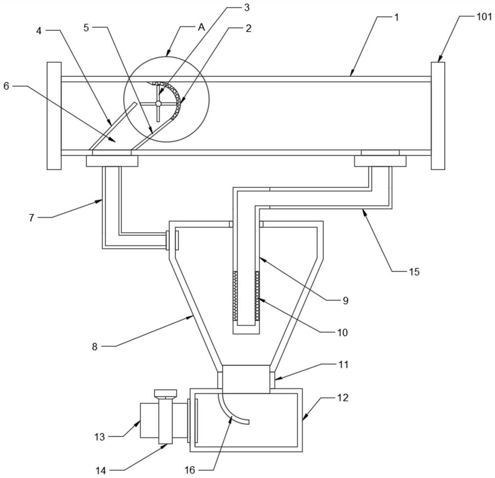
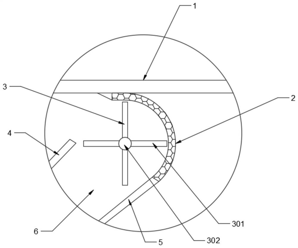
[0020] see Figure 1-3 , in an embodiment of the present invention, a pipeline sewage device for water conservancy projects, including a device body; the device body includes a splicing main pipe 1, and connecting flanges 102 are provided at both ends of the splicing main pipe 1, and are connected and fixed to the outside through the connecting flange 102 ; The splicing main pipe 1 is provided with a filter cover 2, the filter cover 2 intercepts the sludge in the splicing main pipe 1, the filter cover 2 is a hemispherical filter, the filter cover 2 is located on the upper part of the splicing pipe 1 and is connected to the splicing main pipe 1 The top wall is fixedly connected; the front side of the filter cover 2 is provided with a first deflector 4, the first deflector 4 is arranged obliquely, and the first deflector 4 is fixedly connected with the bottom wall of the splicing main pipe 1; the first deflector 4. Guide the water flow of the spliced ​​main pipe 1 to the upper h...

Embodiment 2

[0025] In an embodiment of the present invention, a pipeline sewage device for water conservancy projects includes a device body; the device body includes a splicing main pipe 1, and connecting flanges 102 are provided at both ends of the splicing main pipe 1, and are connected and fixed to the outside through the connecting flange 102; The splicing main pipe 1 is provided with a filter cover 2, and the filter cover 2 intercepts the sludge in the splicing main pipe 1. The filter cover 2 is a hemispherical filter net, and the filter cover 2 is located on the upper part of the splicing pipe 1 and is on top of the splicing main pipe 1. The wall is fixedly connected; the front side of the filter cover 2 is provided with a first deflector 4, the first deflector 4 is arranged obliquely, and the first deflector 4 is fixedly connected with the bottom wall of the splicing main pipe 1; the first deflector 4 The water flow of the spliced ​​main pipe 1 is directed to the upper half of the ...


PUM


Abstract

The invention discloses a pipeline sewage discharge device for hydraulic engineering. The device comprises a device body; the device body comprises a splicing main pipe; a filter hood is arranged in the splicing main pipe; a first guide pipe is arranged at the front side of the filter hood; a second guide pipe is fixedly connected to the bottom of the filter hood; a liquid feeding pipe is fixedlyconnected to the lower part of the splicing main pipe; and the tail end of the liquid feeding pipe communicates with a sedimentation cylinder. The filter hood, the first guide plate, the second guideplate, the liquid feeding pipe, the sedimentation cylinder, a central pipe, a filter screen and a return pipe are arranged to intercept sludge and guide the sludge to the sedimentation cylinder through a guide channel, so that the sludge sedimentation is accelerated, the water after the sludge is removed flows back, the continuous pipeline cleaning without cutting off is realized, and the sludge removal effect is better; and an autorotation impeller including an impeller plate and a rotating shaft is arranged, so that the rotation of the autorotation impeller is achieved under the cooperationof the guide plate, the sludge on the inner wall of the filter hood is scraped off and driven, the filter hood is avoided from being plugged and the sludge is driven to move at the same time, and sludge collection and sedimentation are accelerated.

Description

technical field [0001] The invention relates to the field of water conservancy projects, in particular to a pipeline sewage discharge device for water conservancy projects. Background technique [0002] Pipelines are prone to clogging during the process of conveying sewage. Traditional pipeline cleaning needs to cut off the flow of the pipeline for operation, and at the same time, it is prone to re-blocking. Contents of the invention [0003] The object of the present invention is to provide a pipeline sewage discharge device for water conservancy projects, so as to solve the problems raised in the above-mentioned background technology. [0004] To achieve the above object, the present invention provides the following technical solutions: [0005] A pipe sewage discharge device for water conservancy projects, comprising a device body; the device body includes a spliced ​​main pipe, a filter cover is provided inside the spliced ​​main pipe, a first guide plate is provided ...

Claims


Application Information

Patent Timeline
IPC IPC(8): E03F3/04E03F5/14
CPCE03F3/04E03F5/14
Inventor 张传华
Owner 张传华
Why Eureka
Try Eureka