Pot state detection device for cooker and detection method

A state detection device and state detection technology, which is applied in the direction of household stoves, household appliances, household stoves/stoves, etc., can solve the problems of low reliability and poor precision, and achieve the effect of high sensitivity

Inactive Publication Date: 2020-10-30
VATTI CORP LTD
View PDF17 Cites 1 Cited by
  • Summary
  • Abstract
  • Description
  • Claims
  • Application Information

AI Technical Summary

Problems solved by technology

[0004] In order to solve the above problems, the present invention provides a cooking utensil state detection device, which determines the state of the cooking utensils through the mutual cooperation between the light source assembly and the photosensitive device assembly. This non-contact detection device avoids the There are problems of poor precision and low reliability caused by the detection device

Method used


Image

  • Pot state detection device for cooker and detection method
  • Pot state detection device for cooker and detection method

Examples


Embodiment 1

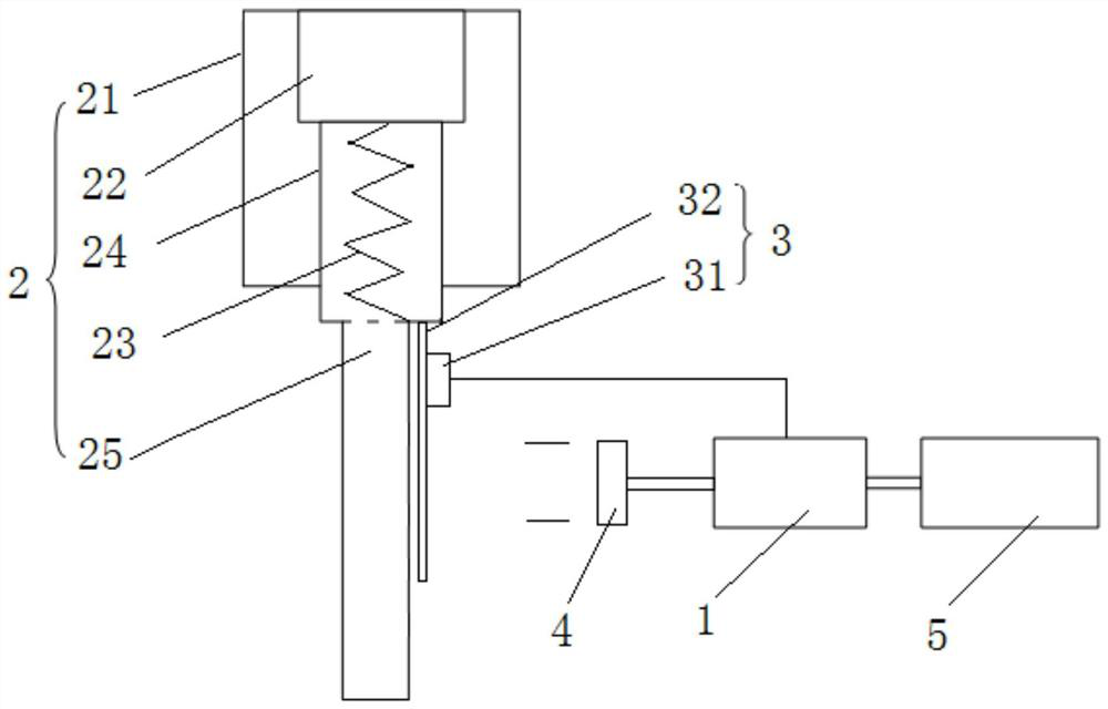
[0036] Embodiment 1 of the present invention provides a cooker state detection device for cooker, such as figure 1 As shown, it includes a controller 1, a telescopic assembly 2, a light source assembly 3, a photosensitive device assembly 4 and a cooker body 5. The light source assembly 3 is fixed on the telescopic assembly 2 and moves up and down with the telescopic assembly 2. The photosensitive device assembly 4 Sensing the light of the light source assembly 3, and controlling the on-off of the photosensitive device assembly 4 through the light, the controller 1 is electrically connected to the cooker body 5 for controlling the firepower of the cooker according to the on-off of the photosensitive device assembly 4;

[0037] In this way, with the above-mentioned structure, when the pot is in the state of the pot, the pot abuts on the top of the telescopic assembly 2, and the telescopic assembly 2 moves downward under the pressure of the pot, driving the light source assembly 3...

Embodiment 2

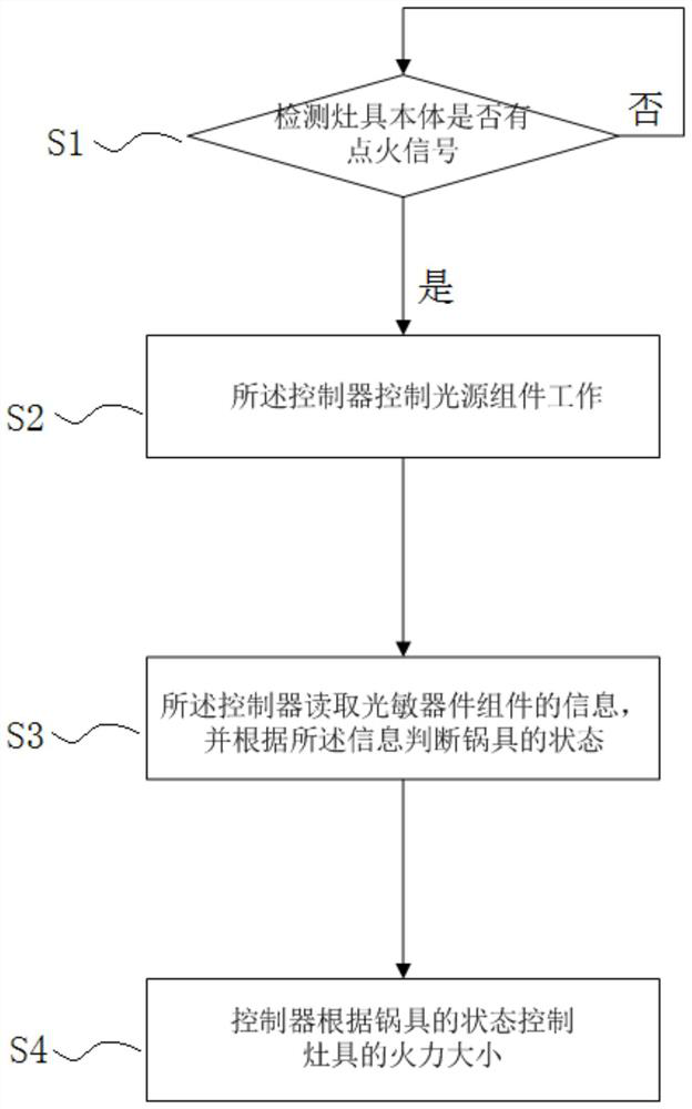
[0055] Embodiment 2 of the present invention provides a method for detecting the state of a cooking utensil, such as figure 2 As shown, the pot state detection device for a cooker described in the application embodiment 1 specifically includes the following steps:

[0056] S1, detect whether the cooker body 5 has an ignition signal, if so, execute S2, otherwise continue to detect;

[0057] S2, the controller 1 controls the light source assembly 3 to work;

[0058] S3, the controller 1 reads the information of the photosensitive device assembly 4, and judges the state of the pot according to the information;

[0059] S4, the controller 1 controls the firepower of the cooker according to the state of the cooker.

[0060] In this way, the photosensitive device assembly 4 is not physically connected with the telescopic assembly 2, and the state of the pot can be judged. Compared with the traditional method of detecting the state of the pot through temperature, it has higher sen...


PUM


Abstract

The invention discloses a pot state detection device for a cooker and a detection method. The detection device includes a controller, a telescopic assembly, a light source assembly, a photosensitive device assembly and a cooker body. The light source assembly is fixed on the telescopic assembly and moves upwards and downwards along with the telescopic assembly. The photosensitive device assembly senses the light of the light source assembly, the on-off of the photosensitive device assembly is controlled through the light, and the controller and the cooker body are connected to control the firepower of the cooker according to the on-off of the photosensitive device assembly. The state of a pot is determined through the interaction between the light source assembly and the photosensitive device assembly, since the photosensitive device assembly is not physically connected to the telescopic assembly, the state of the pot can be judged, compared with a traditional method of detecting the state of the pot through temperature, the sensitivity is higher, and physical structural fatigue caused by long-term use of traditional physical devices such as springs, compression springs and micro switches is avoided.

Description

technical field [0001] The invention belongs to the technical field of pan state detection, and in particular relates to a pan state detection device and detection method for cookers. Background technique [0002] The traditional method for detecting the state of the pot on the cooker is: install a retractable temperature measuring probe on the cooker, and detect it through the change of temperature; the principle is: when the cooker leaves the pot support, the temperature measuring probe is extended, At this time, the flame will directly burn to the temperature measuring probe, so the temperature changes quickly. When the pot is on the pot support, the temperature measuring probe will test the temperature of the pot, and the temperature changes slowly. Therefore, the temperature change rate can be Detect whether the pot is away from the pot or the pot; or directly install springs, compression springs, micro switches, etc. on the retractable temperature measuring probe to de...

Claims


Application Information

Patent Timeline
Patent Type & Authority Applications(China)
IPC IPC(8): F24C3/12F24C15/10G01V8/10
CPCF24C3/126F24C15/107G01V8/10
Inventor 陈敏潘叶江
Owner VATTI CORP LTD
Why Eureka
Try Eureka