A gas valve for a cooker burner

A burner, gas valve technology, applied in the direction of sliding valve, valve details, valve device, etc., can solve the problem of inability to achieve precise control, and achieve the effect of achieving firepower and convenient use

Active Publication Date: 2016-06-29
湖州市双林工业园区开发有限公司
View PDF9 Cites 0 Cited by
  • Summary
  • Abstract
  • Description
  • Claims
  • Application Information

AI Technical Summary

Problems solved by technology

The problem is that precise control cannot be achieved

Method used


Image

  • A gas valve for a cooker burner
  • A gas valve for a cooker burner
  • A gas valve for a cooker burner

Examples


Embodiment Construction

[0023] The present invention will be further described below in conjunction with the accompanying drawings.

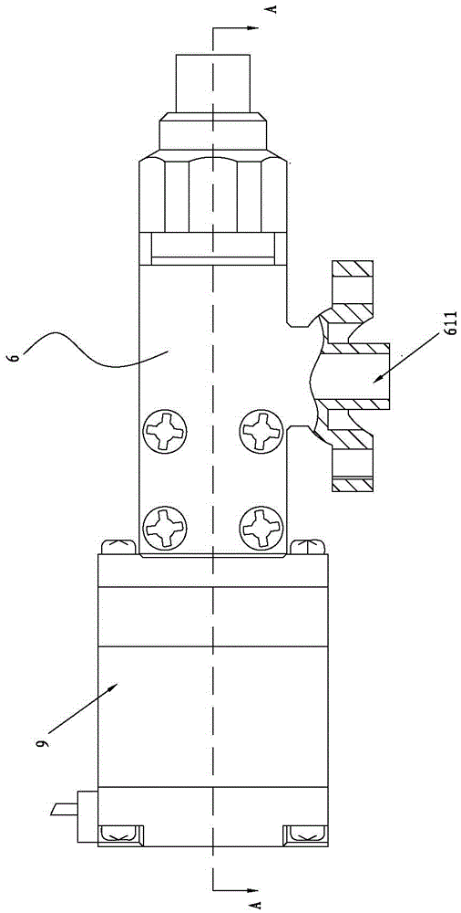
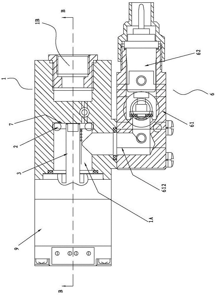
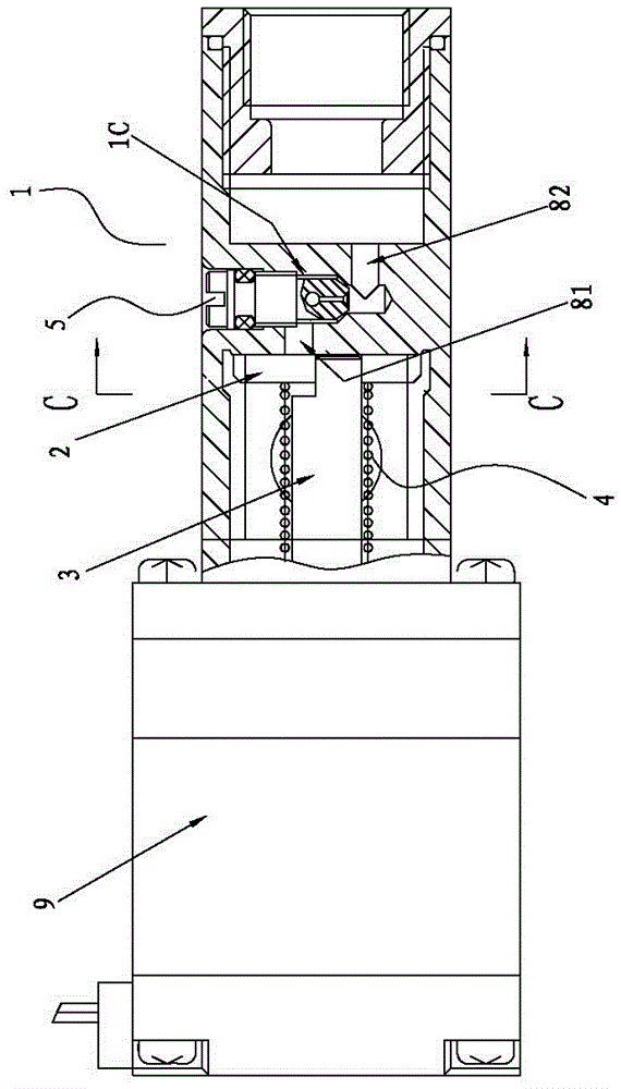
[0024] Such as figure 1 , figure 2 , image 3 As shown, a gas valve for a stove burner includes a valve body 1, a valve core 2, a valve stem 3, a pressure spring 4, a fine-tuning nail 5 and a solenoid valve 6, and the solenoid valve 6 includes a solenoid valve seat 61 and a solenoid valve The core body 62 and the solenoid valve seat 61 have an air inlet port 611 and an air outlet port 612 .

[0025] The valve body 1 includes an air inlet chamber 1A, an air outlet 1B and an air guide chamber 1C, the wall plate at the adjacent end of the inlet chamber 1A and the air outlet 1B is a valve core seat 7, and the valve core seat 7 has a first air guide channel 81 It communicates with the air guide chamber 1C, the air guide chamber 1C communicates with the air outlet 1B through the second air guide channel 82, and the fine-tuning nail 5 is screwed into the air guide chamber...


PUM


Abstract

A gas valve of a stove burner comprises a valve body, a valve element, a vale rod, a pressure spring, a fine tuning pin and an electromagnetic valve. The valve body comprises a gas inlet cavity, a gas outlet and a gas guide cavity. The wall plate of the adjacent ends of the gas inlet cavity and the gas outlet is a valve element seat. The valve element seat is provided with a first gas guide passage communicated with the gas guide cavity. The gas guide cavity is communicated with the gas outlet through a second gas guide passage. The fine tuning pin is screwed to the gas guide cavity. The circular valve element is provided with a gas guide hole. The valve element and the valve element seat are fitted and in hermetic seal. The valve rod is fixedly connected with valve element. The end wall plate, opposite to the valve element seat, of the gas inlet cavity is provided with a valve rod passage. The valve rod and the valve rod passage are rotatably matched and in hermitic seal. One end of the pressure spring is matched with the valve element, and the other end thereof is matched with the end wall plate of the gas inlet cavity. An electromagnetic valve seat is communicated with the gas inlet cavity. By the structure, when the valve element rotates, the gas guide hole of the valve element coincides with the first gas guide passage to precisely adjust gas inlet amount so as to adjust the fire of the burner, and use convenience is achieved.

Description

technical field [0001] The invention relates to a gas valve for a cooker. Background technique [0002] In the current prior art, a gas valve for a stove burner includes a valve body, a valve core, a valve stem, a pressure spring and a solenoid valve, and the solenoid valve includes a solenoid valve seat and a solenoid valve core body. The problem is that precise control cannot be realized. Contents of the invention [0003] The object of the present invention is to provide a gas valve for a cooker burner, which can realize precise control of gas ventilation and firepower adjustment. [0004] The present invention is achieved in the following way: a gas valve for a stove burner, including a valve body, a valve core, a valve stem, a pressure spring, a fine-tuning nail and a solenoid valve, and the solenoid valve includes a solenoid valve seat and a solenoid valve core body; The special feature is that the valve body includes an air inlet chamber, an air outlet and an air ...

Claims


Application Information

Patent Timeline
Patent Type & Authority Patents(China)
IPC IPC(8): F16K3/04F16K3/314F16K3/32F16K27/04F16K31/04
CPCF16K3/06F16K3/314F16K3/32F16K27/045F16K31/046
Inventor 陈顺发
Owner 湖州市双林工业园区开发有限公司
Why Eureka
Try Eureka