
Quality inspection equipment for bottom of bridge and implementation method of quality inspection equipment

A bridge and equipment technology, applied in the field of quality inspection equipment at the bottom of the bridge, can solve the problems of long detection time, high risk factor, difficulty in comprehensive detection, and troublesome detection of the bottom of the bridge, so as to eliminate hidden dangers of bridge problems and avoid electric lifting poles damage, detection part clear effect

Inactive Publication Date: 2020-10-30
张靖
View PDF0 Cites 0 Cited by
  • Summary
  • Abstract
  • Description
  • Claims
  • Application Information

AI Technical Summary

Problems solved by technology

[0003] In the process of using the bridge, it is necessary to inspect the bridge from time to time, especially the inspection of the bottom of the bridge. However, when inspecting the bottom of the bridge between the piers, the inspectors who use the tower crane need to inspect one by one, and the amount of manual operation is large. The detection speed is slow, and it also occupies a separate tower crane. It is more troublesome to detect the bottom of the bridge directly above the small river, and it is even difficult to conduct a comprehensive detection. Moreover, due to the long detection time and the high risk factor, the existing detection using drones is difficult to operate. Affected by the wind, the shaking range is large, and the detection is difficult to achieve comprehensively

Method used


Image

  • Quality inspection equipment for bottom of bridge and implementation method of quality inspection equipment
  • Quality inspection equipment for bottom of bridge and implementation method of quality inspection equipment
  • Quality inspection equipment for bottom of bridge and implementation method of quality inspection equipment

Examples


Embodiment approach

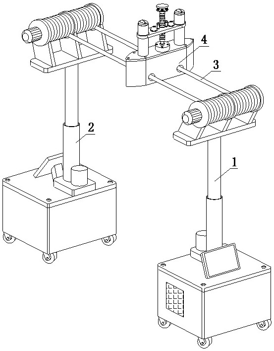
[0045] In order to better demonstrate the implementation process of the quality inspection at the bottom of the bridge, this embodiment now proposes an implementation method for the quality inspection equipment at the bottom of the bridge, including the following steps:

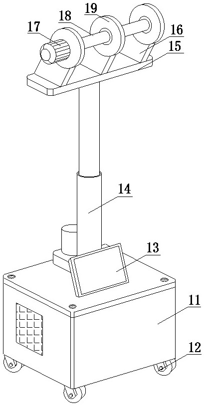
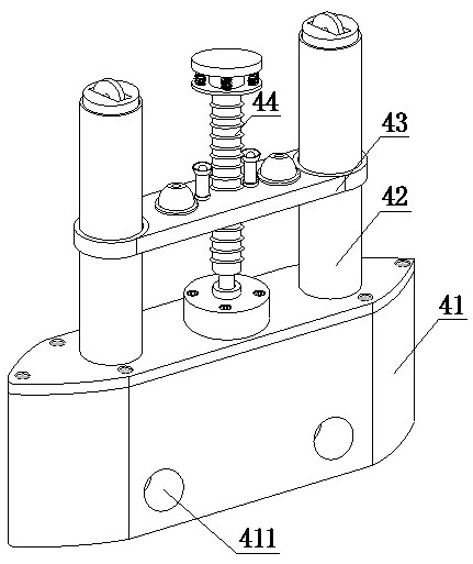
[0046] Step 1: Put the first observation control mechanism 1 and the second observation control mechanism 2 on the guardrails of two adjacent bridge piers respectively, and the two conductive ropes 3 at the upper end of the first observation control mechanism 1 pass through the detection mechanism 4 respectively, Pull the conduction rope 3 to the second observation control mechanism 2 from the bridge again, and wind the conduction rope 3 outside the rotating rod 18 on the second observation control mechanism 2 upper ends;

[0047] Step 2: the first motor 17 of the first observation control mechanism 1 and the second observation control mechanism 2 rotate in reverse direction at the same time, until the conduct...


PUM


Abstract

The invention discloses quality inspection equipment for the bottom of a bridge and an implementation method of the quality inspection equipment. The equipment comprises a first observation control mechanism, a second observation control mechanism, conduction ropes and a detection mechanism, wherein the number of the conduction ropes is two, one end of the conduction rope is wound at the upper endof the first observation control mechanism; and the other end of the conduction rope penetrates through the detection mechanism and wound at the upper end of the second observation control mechanism.The equipment has the beneficial effects that the detection is purely electrically controlled, the physical output of manual detection is reduced, the detection speed is greatly improved, the detection comprehensiveness is high, omission is avoided, the moving stability of the detection mechanism is improved, shooting of the camera is clearer, the detection is more accurate, hidden dangers of bridge problems are eliminated to the maximum extent, a searchlight can be turned on due to the fact that the bottom of the bridge is dark so as to ensure that the detection part is clear, the two overlooking sides of a mounting box are sharp-angled, wind resistance of the lower end of the bridge borne by the detection mechanism is reduced, and the detection accuracy is guaranteed.

Description

technical field [0001] The invention relates to the technical field of building quality inspection equipment, in particular to a quality inspection equipment used at the bottom of a bridge and an implementation method thereof. Background technique [0002] Bridges generally refer to structures erected on rivers, lakes and seas to allow vehicles and pedestrians to pass smoothly. In order to adapt to the modern high-speed development of the transportation industry, bridges are also extended to buildings that cross mountain streams, poor geology or meet other transportation needs to make traffic more convenient. A bridge is generally composed of a superstructure, a substructure, a support and ancillary structures. The superstructure is also called a bridge span structure, which is the main structure for crossing obstacles; the substructure includes abutments, piers and foundations; Or the force transmission device installed at the supporting place of the bridge abutment; the a...

Claims


Application Information

Patent Timeline
Patent Type & Authority Applications(China)
IPC IPC(8): G01N21/01G01N21/95
CPCG01N21/01G01N21/9515
Inventor 张靖
Owner 张靖
Learn More