
An automotive optical fiber Ethernet communication device

A communication device, Ethernet technology, applied in the field of Ethernet communication, can solve problems such as poor scalability, expensive requirements, and complexity of hardware debugging, and achieve the effects of improving EMC performance, reducing complexity and cost, and excellent EMC performance

Active Publication Date: 2022-01-11
深圳市周立功单片机有限公司
View PDF12 Cites 0 Cited by
  • Summary
  • Abstract
  • Description
  • Claims
  • Application Information

AI Technical Summary

Problems solved by technology

[0002] The application of new technologies in automobiles puts forward higher requirements for the bandwidth of automobile networks, which promotes the explosive growth of bandwidth demand for automobile networks. However, traditional automobile networks have low bandwidth or high cost and poor scalability, making it difficult to meet the various needs of automobile manufacturers.
[0003] Ethernet was born early and has the advantages of mature technology, high bandwidth, low cost and strong scalability. It has been widely used before entering the automotive field. Due to the high transmission bandwidth of Ethernet, it leads to higher energy emissions. (Electromagnetic Compatibility) requirements are very strict, so that Ethernet has not achieved technological breakthroughs in recent years and can be used in automobiles, that is, automotive single-pair twisted pair (100Base-T1 / 1000Base-T1 standard), but in its development process, Need to do a series of professional standard tests (such as PMA test), and the need to pass these tests not only requires expensive instruments, but also the complexity of hardware debugging will undoubtedly lead to more costs
[0004] The electrical environment in the car is complex. For safety reasons, the key nodes need to be galvanically isolated to prevent short circuits. However, the existing automotive twisted-pair Ethernet communication system has poor EMC performance and is difficult to meet the requirements for galvanic isolation.

Method used


Image

  • An automotive optical fiber Ethernet communication device
  • An automotive optical fiber Ethernet communication device

Examples


Embodiment Construction

[0023] In order to make the purpose, technical solution and advantages of the present application clearer, specific embodiments of the present application will be further described in detail below in conjunction with the accompanying drawings. It should be understood that the specific embodiments described here are only used to explain the present application, but not to limit the present application. In addition, it should be noted that, for the convenience of description, only parts relevant to the present application are shown in the drawings but not all content.

[0024] In the description of the embodiments of this application, unless otherwise specified and limited, the terms "connected", "connected" and "fixed" should be understood in a broad sense, for example, it can be a fixed connection or a detachable connection, or Integrate; can be mechanical connection, can also be electrical connection; can be directly connected, can also be indirectly connected through an inte...


PUM


Abstract

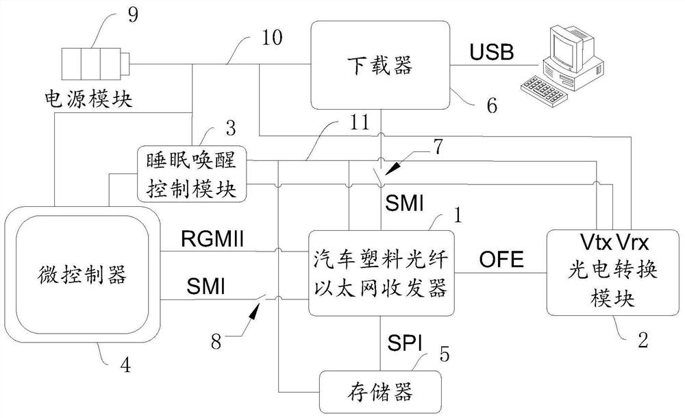
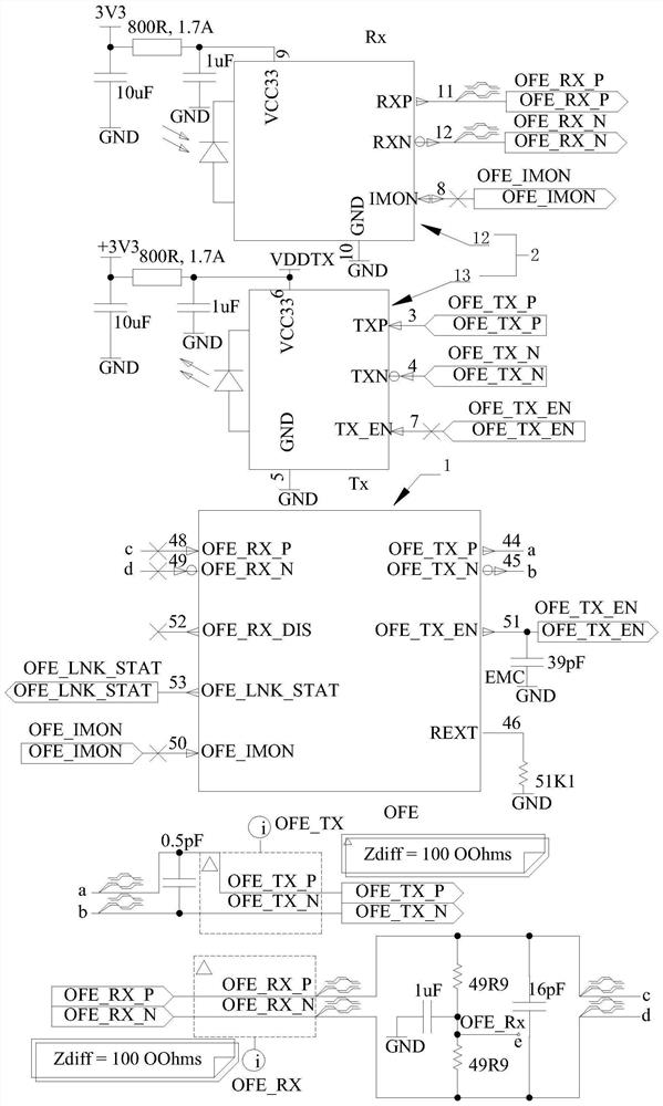
The embodiment of the present application discloses an automotive optical fiber Ethernet communication device. The technical solution provided by the embodiment of the present application controls the work of the sleep wake-up module through the control module. When the automotive optical fiber Ethernet communication is required, the sleep wake-up module is controlled to power on the optical fiber Ethernet transceiver and the photoelectric conversion module, and communication is required. The photoelectric conversion module is connected between the two nodes of the line through optical fiber to realize the Ethernet data transmission between the two communication nodes. Control, using optical fiber communication to play the role of galvanic isolation, also because of its excellent EMC performance, reduces the complexity and cost of the EMC debugging process, improves the EMC performance of automotive Ethernet, and meets the requirements for galvanic isolation.

Description

technical field [0001] The embodiment of the present application relates to the field of Ethernet communication, in particular to an automotive optical fiber Ethernet communication device. Background technique [0002] The application of new automotive technologies puts forward higher requirements for the bandwidth of automotive networks, driving the explosive growth of automotive network bandwidth demand. However, traditional automotive networks have low bandwidth or high costs and poor scalability, making it difficult to meet the various needs of automotive manufacturers. [0003] Ethernet was born early and has the advantages of mature technology, high bandwidth, low cost and strong scalability. It has been widely used before entering the automotive field. Due to the high transmission bandwidth of Ethernet, it leads to higher energy emissions. (Electromagnetic Compatibility) requirements are very strict, so that Ethernet has not achieved technological breakthroughs in rec...

Claims


Application Information

Patent Timeline
Patent Type & Authority Patents(China)
IPC IPC(8): H04B10/27H04B10/80H04L12/12
CPCH04B10/27H04B10/801H04B10/808H04L12/12Y02D30/50
Inventor 周立功陈超鹏
Owner 深圳市周立功单片机有限公司
Learn More