Power generation control device for vehicle generator

a technology for power generation control and vehicle generators, applied in the direction of electric generator control, dynamo-electric converter control, generation protection through control, etc., can solve problems such as malfunction of communication receivers

Inactive Publication Date: 2009-08-18
DENSO CORP
View PDF37 Cites 5 Cited by
  • Summary
  • Abstract
  • Description
  • Claims
  • Application Information

AI Technical Summary

Benefits of technology

[0010]According to the present invention, EMC performance of a communication circuit included in a power generation control device for a vehicle generator can be easily improved without incurring high costs because of the structure in which a resistor is mounted as an external component to the IC circuit in order to attenuate external electrical noise arrived at a communication terminal of the power generation control device through a communication wire.
[0016]Preferably, the resistor is disposed away from the IC circuit by such a distance that the IC circuit is not affected by electromagnetic noise occurring when electrical noise arriving at the communication terminal is attenuated in the resistor.

Problems solved by technology

However, the conventional voltage control device as disclosed in this document has a problem in that the communication receiver thereof may be caused to malfunction if electrical noise goes into the communication circuit through the communication wire and the communication terminal.
Such electrical noise includes ESD (Electric Static Discharge), CI noise, and RI noise.

Method used


Image

  • Power generation control device for vehicle generator
  • Power generation control device for vehicle generator
  • Power generation control device for vehicle generator

Examples


Embodiment Construction

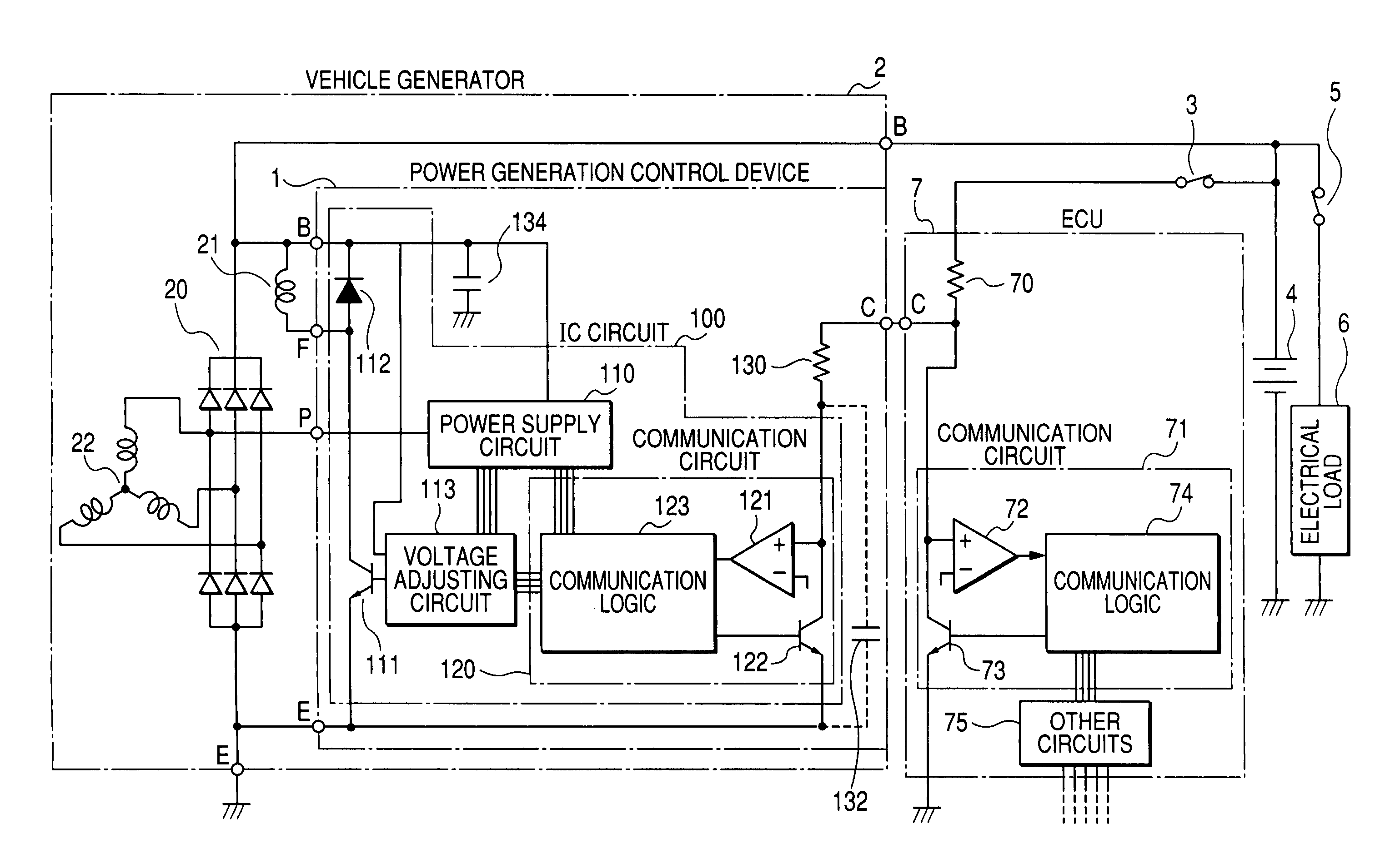
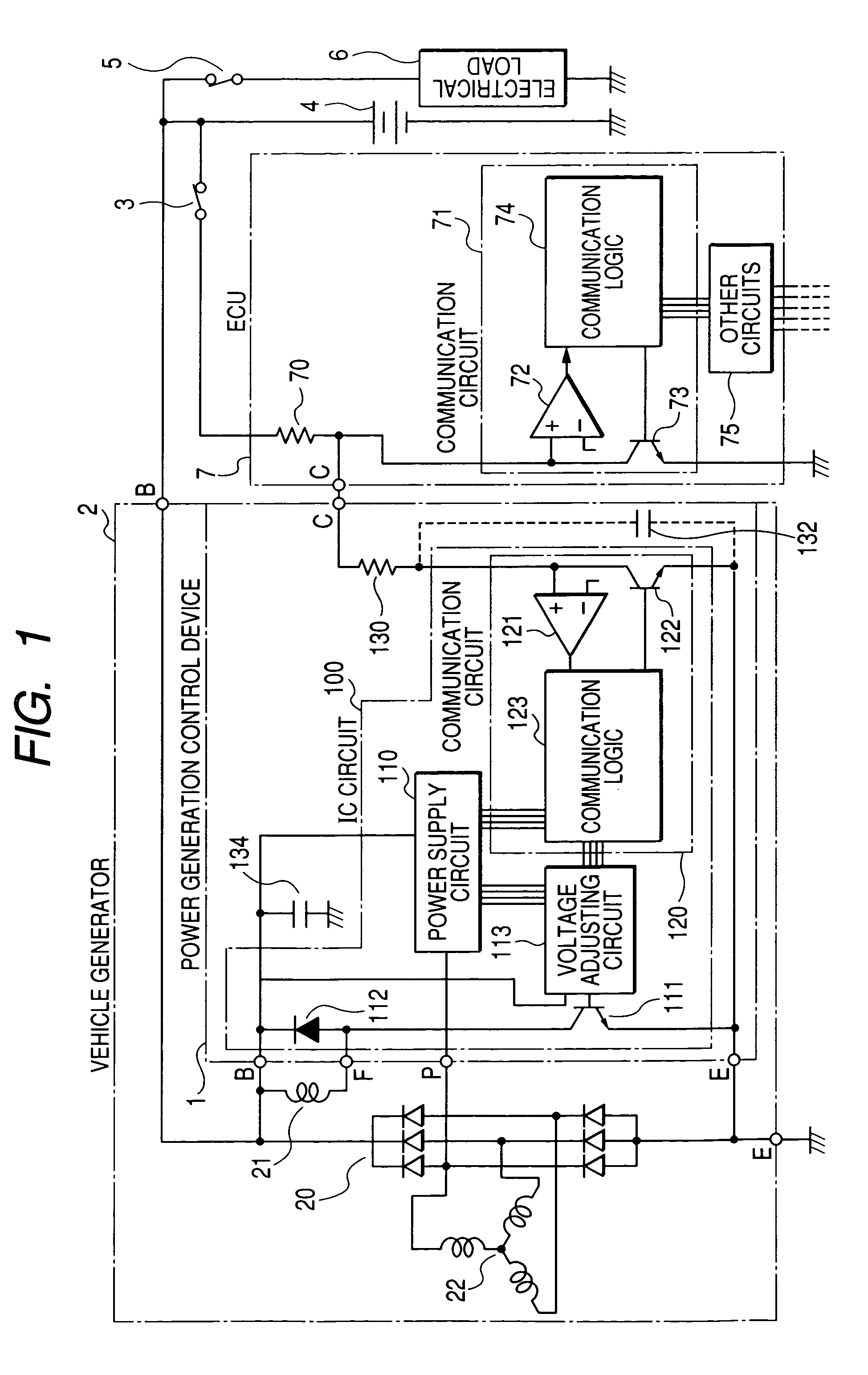
[0022]FIG. 1 is a block diagram showing an electrical structure of a vehicle generator 2 including a power generation control device 1 according to an embodiment of the invention connected to a vehicle battery 4, an ECU (Electronic Control Unit) 7 as an external control unit, and an electrical load 6.

[0023]As show in this figure, the vehicle generator 2 is constituted by a rectifier 20, a rotor having a field winding 21 wound around magnetic poles thereof, an armature having a multi-phase (three-phase, for example) armature winding 22 wound around an armature core thereof, and the power generation control device 1. The vehicle generator 2 is belt-driven by a vehicle engine (not shown) The field winding 21 generates a rotating magnetic field by being supplied with an excitation current. This rotating magnetic field induces an electromotive force (AC voltage) in the armature winding 22. The AC voltage induced in the armature winding 22 is full-wave rectified by the rectifier 20. The o...


PUM


Abstract

The power generation control device for a vehicle generator includes an IC circuit including a communication circuit formed therein and having a function of performing a digital communication with an external device through a communication wire, and a resistor mounted to the IC circuit so as to connect the communication circuit to a communication terminal of the power generation control device connected to the communication wire.

Description

CROSS-REFERENCE TO RELATED APPLICATION[0001]This application is related to Japanese Patent Application No. 2005-302508 filed on Oct. 18, 2005, the contents of which are hereby incorporated by reference.BACKGROUND OF THE INVENTION[0002]1. Field of the Invention[0003]The present invention relates to a power generation control device for controlling a power generation state of a vehicle generator mounted on a vehicle such as a passenger car or a truck.[0004]2. Description of Related Art[0005]There is known a configuration in which a two-way communication is performed between a voltage control device included in a vehicle generator and an engine control device as disclosed, for example, in U.S. Pat. No. 6,567,476. As disclosed in this document, the voltage control device of the vehicle generator includes a communication circuit having a voltage comparator serving as a communication receiver and a switching transistor serving as a communication driver which are both connected to a commun...

Claims


Application Information

Patent Timeline
Patent Type & Authority Patents(United States)
IPC IPC(8): H02P11/00H02H7/06H02P9/00
CPCH02P9/006H02K11/0078H02K11/35
Inventor MARUYAMA, TOSHINORIOSHIMA, KENJI
Owner DENSO CORP
Why Eureka
Try Eureka