
Improved pressure transmitter

A transmitter and an improved technology, applied in the direction of measuring fluid pressure, measuring fluid pressure through electromagnetic components, instruments, etc., can solve the problems of high cost, large volume, and complex structure of pressure transmitters, and achieve simple structure and improved performance. EMC performance, effect of improving stability and reliability

Active Publication Date: 2013-11-27
SHANGHAI JUNLE REFRIGERATION CONTROL
View PDF6 Cites 5 Cited by
  • Summary
  • Abstract
  • Description
  • Claims
  • Application Information

AI Technical Summary

Problems solved by technology

[0003] However, the above-mentioned connection and packaging structure results in high cost, complex structure and large volume of the pressure transmitter.

Method used


Image

  • Improved pressure transmitter
  • Improved pressure transmitter
  • Improved pressure transmitter

Examples


Embodiment Construction

[0032] In order to make the technical means, creative features, goals and effects achieved by the present invention easy to understand, the present invention will be further described below in conjunction with specific illustrations.

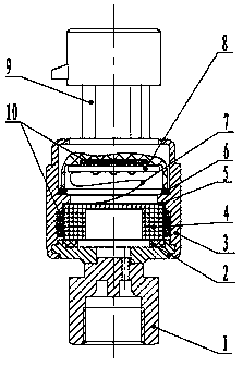
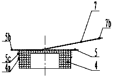
[0033] see figure 1 , which shows a cross-sectional view of the pressure transmitter in this example. It can be seen from the figure that the pressure transmitter is mainly composed of a joint part 1, a rectangular ring 2, a housing 3, a sensitive element 4, an insulating diaphragm 5, a sealing ring 6, a cable 7, a circuit board 8, an electrical plug-in 9 and epoxy resin 10 compositions.

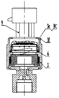
[0034] In this pressure transmitter, the joint part 1 and the electrical plug-in 9 are respectively placed on the casing 3 to constitute the main structure of the entire pressure transmitter, and the electrical components such as the sensitive element 4 and the circuit board 8 are placed through the corresponding sealing and isolation parts Within the main s...


PUM


Abstract

The invention discloses an improved pressure transmitter. A connector component of a packaging structure of the improved pressure transmitter is connected with a boiler or a pressure container or a pressure pipeline to provide a pressure source for a sensitive element. The improved pressure transmitter is connected with an outer shell through a circuit board, carries out shielding on the circuit board, and improves the EMC performance. Meanwhile, the connector component and the outer shell are packaged through a split-body riveting connecting structure, the outer shell and an electrical insertion part are connected in a riveting mode, and a corresponding seal ring, the corresponding sensitive element and the corresponding circuit board are installed in the shell body. Due to the fact the simple packaging structure is adopted, the improved pressure transmitter is simple in structure, facilitates technology adjustment, and reduces manufacturing cost.

Description

technical field [0001] The invention relates to a pressure transmitter. Background technique [0002] At present, pressure transmitter packages based on sensitive components such as ceramic sensors or diffused silicon pressure sensors mainly adopt an integrated structure. A screw is used to press the sensitive component on the lower side of the inner cavity, and O is used between the sensitive component and the inner cavity. The inner cavity is connected to the boiler, pressure vessel or pressure pipeline through an interface; the other end transmits the conditioned and amplified signal through the connector; between the connector and the package shell, silicone or ring is used. Oxygen and other methods are connected and sealed. [0003] However, the above connection and packaging structure results in high cost, complex structure and large volume of the pressure transmitter. Contents of the invention [0004] The invention provides an improved pressure transmitter aiming...

Claims


Application Information

Patent Timeline
Patent Type & Authority Applications(China)
IPC IPC(8): G01L9/00
Inventor 冯志军补灵杰叶国兴
Owner SHANGHAI JUNLE REFRIGERATION CONTROL
Learn More