Garden design trimmer and trimming method thereof

A pruner and gardening technology, which is applied in the field of garden design pruners and their pruning, can solve the problem that the pruning size of trees cannot be adjusted, and achieve the effect of increasing the aesthetic feeling

Inactive Publication Date: 2020-11-03
刘耀军
View PDF1 Cites 5 Cited by
  • Summary
  • Abstract
  • Description
  • Claims
  • Application Information

AI Technical Summary

Problems solved by technology

But the device can not adjust the size of tree pruning

Method used


Image

  • Garden design trimmer and trimming method thereof
  • Garden design trimmer and trimming method thereof
  • Garden design trimmer and trimming method thereof

Examples


specific Embodiment approach 1

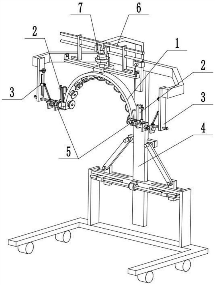
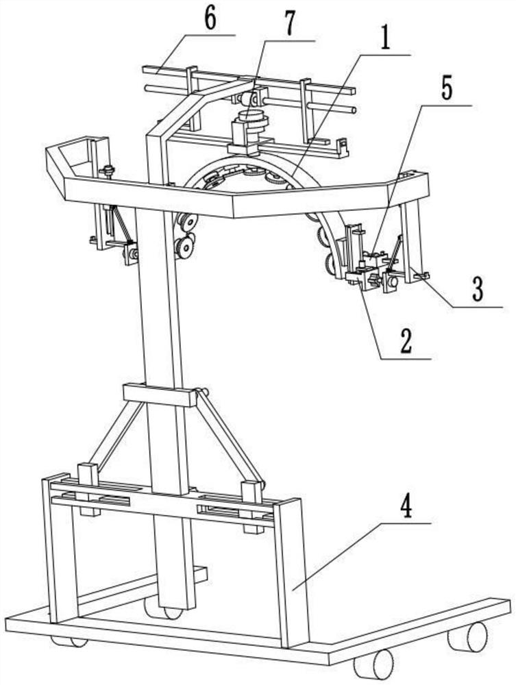
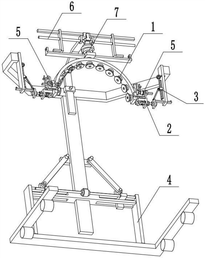
[0035] Combine below Figure 1-9 Description of this embodiment, a garden design trimmer, including a main trimmer 1, a side insert 2, a side rotation control mechanism 3, a frame 4, a side trimmer 5, an upper fixed insert 6 and an upper rotary drive 7, the The two ends of the main trimmer 1 are respectively provided with a side insert 2, and the two side inserts 2 are respectively connected with two side rotation control mechanisms 3, and the two side rotation control mechanisms 3 are symmetrically arranged on the upper end of the frame 4, and the main The two ends of the trimmer 1 are respectively fixedly connected with a side trimmer 5, the upper rotary driver 7 is connected to the main trimmer 1, the upper fixed insert 6 is connected to the upper end of the frame 4, and the two ends of the upper rotary driver 7 are respectively Correspondingly set with the two ends of upper fixed plug-in 6. When in use, move the frame 4 to the vicinity of the trees, adjust the height of t...

specific Embodiment approach 2

[0037] Combine below Figure 1-9 To illustrate this embodiment, the main trimmer 1 includes an arc seat 1-1, a first motor 1-2, a first cutter head 1-3, a T-shaped frame 1-4 and an adjustment block 1-5; The inner end of the seat 1-1 is uniformly surrounded and fixedly connected to a plurality of first motors 1-2, the output shafts of the plurality of first motors 1-2 are respectively fixedly connected to the first cutter head 1-3, and the two ends of the arc-shaped seat 1-1 The ends are respectively fixedly connected with a T-shaped frame 1-4, and the two T-shaped frames 1-4 are respectively fixedly connected with an adjusting block 1-5, and the two adjusting blocks 1-5 are respectively connected with two side inserts 2; The upper end of seat 1-1 is connected with fixed insert 7. In use, when the arc seat 1-1 rotates around a semicircular track or rotates under the drive of the upper rotary drive member 7, multiple first motors 1-2 start to drive multiple first cutter heads 1...

specific Embodiment approach 3

[0039] Combine below Figure 1-9 To illustrate this embodiment, the side insert 2 includes a chute seat 2-1, a T-shaped chute 2-2, a socket 2-3, a through hole 2-4, a convex chute 2-5, and a second motor 2 -6 and the first screw rod 2-7; the inner end of the chute seat 2-1 is provided with a T-shaped chute 2-2, and the T-shaped frame 1-4 is slidingly fitted and connected in the T-shaped chute 2-2, and the chute The outer end of the seat 2-1 is fixedly connected to the socket 2-3, and the socket 2-3 is provided with a through hole 2-4 and four convex chute 2-5, and the four convex chute 2-5 surrounds the through hole 2 -4 is arranged and communicated with the through hole 2-4, the second motor 2-6 is fixedly connected to the socket 2-3 through the motor frame, and the output shaft of the second motor 2-6 is connected to the first screw rod 2-7 through a coupling , the protruding line chute 2-5 is connected to the first screw rod 2-7 through thread fit; the side rotation contro...


PUM


Abstract

The invention discloses a garden design trimmer and a trimming method thereof. The garden design trimmer and the trimming method have the advantages that trees can be trimmed and formed at a time, andthe trees can be trimmed into semicircle shapes of different sizes. The method comprises the steps that 1, a rack is moved to the positions near the trees, and the height of the rack is adjusted to be consistent with the heights of the trees; 2, two side rotation control mechanisms are started to drive a main trimmer to rotate around a semicircular track, and the upper ends of the trees are cut into semicircles at a time; 3, the main trimmer moves up and down to cut the trees into semicircles with different sizes; 4, after an upper rotary driving piece is connected with an upper fixed inserting piece, the two side rotation control mechanisms are separated from two side inserting pieces, and the upper rotary driving piece is started to drive the main trimmer to rotate to trim the trees into the semicircles; and 5, two side trimming pieces extend inwards, and the middle parts of the trees are processed into concave cambered outlines, so that the aesthetic feeling is increased.

Description

technical field [0001] The invention relates to the field of landscaping devices, in particular to a garden design trimmer and a trimming method thereof. Background technique [0002] The existing patent number is CN201921658090.8, a plant pruning device for garden maintenance, a plant pruning device for garden maintenance, including a trolley, a roller is provided at the bottom of the trolley, a handle is provided at one end of the trolley, and the main body of the trolley is a hollow structure , There are at least two "U"-shaped support frames on the top of the trolley, and vertical threaded rods are arranged inside the "U"-shaped support frames. The lower end of the threaded rods passes through the top surface of the trolley and extends to the inside of the trolley. There is a first motor, the rotating shaft of the first motor is set through the top surface of the trolley, and the threaded rod part inside the trolley is connected with the rotating shaft of the first motor...

Claims


Application Information

Patent Timeline
Patent Type & Authority Applications(China)
IPC IPC(8): A01G3/04
CPCA01G3/0435
Inventor 刘耀军
Owner 刘耀军
Why Eureka
Try Eureka