Punch press transmission equipment

A technology of transmission equipment and punching machines, applied in the direction of punching machines, presses, manufacturing tools, etc., can solve problems such as mold gaps, unqualified products, and products that cannot meet the standard quality requirements, and achieve the effect of increasing efficiency

Inactive Publication Date: 2020-11-03
广州国智机电设备有限公司
View PDF0 Cites 0 Cited by
  • Summary
  • Abstract
  • Description
  • Claims
  • Application Information

AI Technical Summary

Problems solved by technology

[0003] In order to solve the problem that the existence of lubricating oil in the above technology will cause gaps between the molds, and the gaps will directly cause the product to fail to meet the standard requirements after stamping and the quality is unqualified. The present invention provides a punch transmission device

Method used


Image

  • Punch press transmission equipment
  • Punch press transmission equipment
  • Punch press transmission equipment

Examples


Embodiment 1

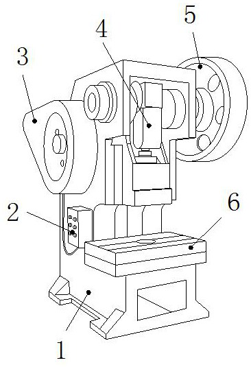
[0024] as attached figure 1 to attach Figure 4 Shown:

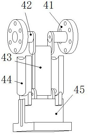
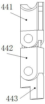
[0025] The present invention provides a transmission device for a punching machine, the structure of which includes a base 1, a controller 2, a lower shaft wheel 3, a transmission stamping head 4, an upper shaft wheel 5, and a stamping table 6, and bolts on the outer side of the middle part of the base 1 and the inner side of the controller 2 connection, the inner side of the lower shaft wheel 3 is axially connected with the base 1, the transmission stamping head 4 is movable and engaged with the upper end of the base 1, the upper shaft wheel 5 is axially connected with the right side of the upper end of the transmission stamping head 4, and the stamping The platform 6 is installed on the upper end of the base 1, and the transmission stamping head 4 includes a runner 41, a crankshaft 42, a connecting rod 43, a degreaser 44, and a punch 45. The crankshaft 42 is embedded and connected to the inside of the runner 41, one ...

Embodiment 2

[0031] as attached Figure 5 to attach Figure 7 Shown:

[0032] Wherein, the bonding head 41e includes a bonding sheet e1, an oil suction pipe e2, a curved rod e3, a push rod e4, a sealing plate e5, a sealing cavity e6, and a wrapping strip e7, and the middle part of the lower end of the bonding sheet e1 is connected to the push rod e4 The upper end shaft is connected, the oil suction pipe e2 is connected between the bonding piece e1 and the oil suction pipe e2, the curved rod e3 is connected between the bonding piece e1 and the wrapping strip e7, and the outer side of the push rod e4 is connected to the sealing cavity e6 The inner surfaces are attached together, the upper side of the sealing plate e5 is welded to the lower side of the push rod e4, the upper end of the sealing chamber e6 is screwed to the oil suction pipe e2, the wrapping strip e7 is connected to the inner shaft of the outer cover 41d, and the oil suction The pipe e2 is made of rubber, which has the charact...


PUM


Abstract

The invention discloses punch press transmission equipment which structurally comprises a base, a controller, a lower shaft wheel, a transmission punching head, an upper shaft wheel and a punching table. The outer side of the middle of the base is in bolt connection with the inner side of the controller, and the transmission punching head is movably clamped with the interior of the upper end of the base; under the cooperation of an adjusting cavity and a fixing block, a partition plate is pushed by a connecting seat and a spring to be compressed, and then an attaching head is attached to a crankshaft under the cooperation of an outer cover to achieve the absorption effect, so that the phenomenon that gaps between molds is caused by existence of lubricating oil, and due to gap generation, aproduct cannot meet the standard requirement after being punched and is unqualified is avoided, a push block of a wrapping strip is pushed to rotate through a rotating shaft and then absorbs the lubricating oil from a bowl opening in a rotating joint through a hollow pipe, in the rotating process, an ejector head is pushed through a contact head, then a main block rotates around a connecting shaft through a bevel, the lubricating oil is absorbed through the bowl opening in an auxiliary block to be conveyed through a pipe cavity, and the crankshaft oil absorption efficiency by an oil remover is improved.

Description

technical field [0001] The invention belongs to the field of transmission equipment, and more specifically, relates to a punch transmission equipment. Background technique [0002] Punch transmission equipment is used to ensure the stability of the transmission of the punch and provide strong pressure. The transmission of the punch is divided into mechanical transmission and hydraulic transmission. During the movement, the lubricating oil will flow to the punch template through the transmission rod, causing the surface of the template to be covered with a layer of lubricating oil. When the finished parts are processed, the existence of the lubricating oil will cause gaps between the molds and gaps. It will directly cause the product to fail to meet the standard requirements after stamping and the quality is unqualified, and after a long period of stamping, the small errors caused by the lubricating oil will be enlarged, resulting in the offset of the transmission rod and the...

Claims


Application Information

Patent Timeline
Patent Type & Authority Applications(China)
IPC IPC(8): B30B1/14B30B15/00
CPCB30B1/14B30B15/0088
Inventor 李工妹
Owner 广州国智机电设备有限公司
Why Eureka
Try Eureka