A real-time detection system for the lift force and ground effect change of plant protection UAV
What is AI technical title?
AI technical title is built by Patsnap AI team. It summarizes the technical point description of the patent document.
A real-time detection and aircraft lift technology, which is applied in the direction of aircraft component testing, etc., can solve the problems that the flying height of the helicopter cannot be strictly controlled, the lift force change and the ground effect change have not been involved, and the strength cannot be changed.
Inactive Publication Date: 2021-10-29
CHINA AGRI UNIV
View PDF0 Cites 0 Cited by
Summary
Abstract
Description
Claims
Application Information
AI Technical Summary
This helps you quickly interpret patents by identifying the three key elements:
Problems solved by technology
Method used
Benefits of technology
Problems solved by technology
The detection method in this paper has certain limitations. The flying height of the helicopter cannot be strictly controlled, and it can only detect the change of lift force. It cannot explore the specific distribution of ground effect and the jitter generated by the drone. The attitude change of the machine, the purpose of measurement and the design of the device are all different from those of the present invention
[0006] At present, most of the relevant testing equipment is aimed at the lift test of UAVs at a fixed height, lacking the ability to simulate different operating heights of plant protection UAVs, and has not yet involved the relationship between lift changes and ground effect changes. Intensity change to get ground effect
Method used
Image
Click on the blue label to locate the original text in one second.
Reading with bidirectional positioning of images and text.
Examples
Embodiment Construction
[0036] The present invention will be described in further detail below in conjunction with the accompanying drawings and specific embodiments.
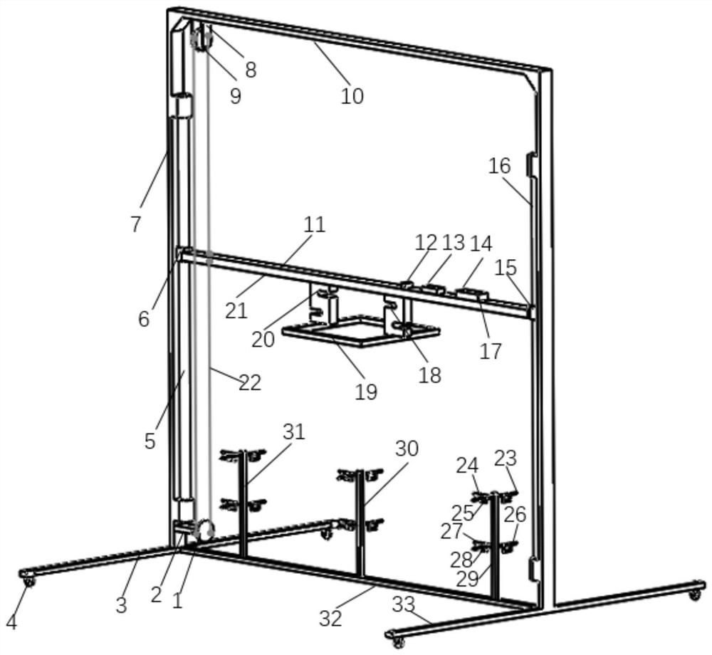
[0037] Such as Figure 1-5 As shown in the present invention, a real-time detection system for the lift force and ground effect change of a plant protection drone. In this embodiment, the pull pressure sensor I18 and the pull pressure sensor II20 use the DYLY-103 pull pressure sensor, and the pull pressure sensor I18 . The upper end of the tension and pressure sensor II 20 is fixed on both sides of the center position of the moving beam 21 by bolts, and the lower end is fixedly connected to the center frame 19 by bolts, and the six-rotor plant protection UAV JF01-10 is bound to the center frame 19 by cable ties 17 , MPU6050 gyroscope 12, Arduino Mega 2560 single-chip microcomputer and wireless communication system 13, power supply 14 are fixed above the right end of the moving beam 21 through cable ties 17, pull pressure sensor I18, p...
PUM
Abstract
The invention relates to a real-time detection system for the lift force and ground effect change of a plant protection drone, including: a small sprocket, a motor, two wheel frames, a polished rod I, a slider I, two trusses, a sprocket seat, a large sprocket, Beams, wires, gyroscopes, microcontrollers and wireless communication systems, power supplies, polished rods II, sliders II, cable ties, pull pressure sensors I, steady frames, pull pressure sensors II, moving beams, chains, pressure sensors I, pressure sensors II , pressure sensor III, pressure sensor IV, pressure sensor V, pressure sensor VI, pressure sensor bracket I, pressure sensor bracket II, pressure sensor bracket III, pressure sensor base, two pressure sensor base polished rods; the plant protection drone of the present invention The height can be adjusted, and it can obtain the attitude change of the plant protection drone and the change of the ground wind field, and analyze the change of the ground effect intensity through the change of lift force and attitude change, which provides a basis for the parameter selection of the actual spraying operation of the plant protection drone.
Description
technical field [0001] The invention relates to a real-time detection system for the lift force and ground effect change of a plant protection drone, which belongs to the field of flight stability testing and evaluation of the plant protection drone. Background technique [0002] In recent years, plant protection UAV technology has developed rapidly and is widely used in the agricultural field. During the plant protection operation, the downwash flow field of the plant protection drone will rebound or hoist when encountering dense objects such as the ground or crop canopy, which is called ground effect (referred to as "ground effect"). Different working heights will form ground effects of different strengths. While the ground effect drives the fog droplets to reach the crop surface, it will also react on the plant protection drone, causing the body of the plant protection drone to shake and lift to change, thereby affecting flight stability. Therefore, it is necessary to d...
Claims
Application Information
Patent Timeline
Application Date:The date an application was filed.
Publication Date:The date a patent or application was officially published.
First Publication Date:The earliest publication date of a patent with the same application number.
Issue Date:Publication date of the patent grant document.
PCT Entry Date:The Entry date of PCT National Phase.
Estimated Expiry Date:The statutory expiry date of a patent right according to the Patent Law, and it is the longest term of protection that the patent right can achieve without the termination of the patent right due to other reasons(Term extension factor has been taken into account ).
Invalid Date:Actual expiry date is based on effective date or publication date of legal transaction data of invalid patent.

