A valve bag vacuum filling equipment

A technology of vacuum filling and valve pockets, applied in the directions of packaging, transportation and packaging, types of packaging items, etc., it can solve the problems of reducing beverage filling efficiency, inability to control the outflow speed, quality changes, etc., to improve filling stability and efficiency. Filling efficiency, ensuring filling purity and quality, and the effect of uniform flow speed

Active Publication Date: 2021-12-10
郑州宝腾科技有限公司
View PDF6 Cites 0 Cited by
  • Summary
  • Abstract
  • Description
  • Claims
  • Application Information

AI Technical Summary

Problems solved by technology

[0004] Aiming at the deficiencies in the prior art, the purpose of the present invention is to provide a valve bag vacuum filling equipment to solve the problem that when filling the valve bag, the beverage is directly passed into the valve bag through the filling head, and the filling The beverage enters the valve pocket through the inner wall of the filling head, and the outer wall of the filling head will be exposed when the filling is stopped, and dust and impurities will adhere to the surface. The filling head is cleaned. If the filling head is not treated, the valve bag is covered on the filling head, and impurities will be brought in when the beverage is filled, which will cause the quality of the material in the valve bag to change; and When the filled beverage is put into the valve pocket, the filled beverage enters the valve pocket quickly through the filling head, and the outflow speed cannot be controlled, causing the filled beverage to overflow and fall to the ground, resulting in waste of the filled beverage and reducing The problem of beverage filling efficiency

Method used


Image

  • A valve bag vacuum filling equipment
  • A valve bag vacuum filling equipment
  • A valve bag vacuum filling equipment

Examples


Embodiment 1

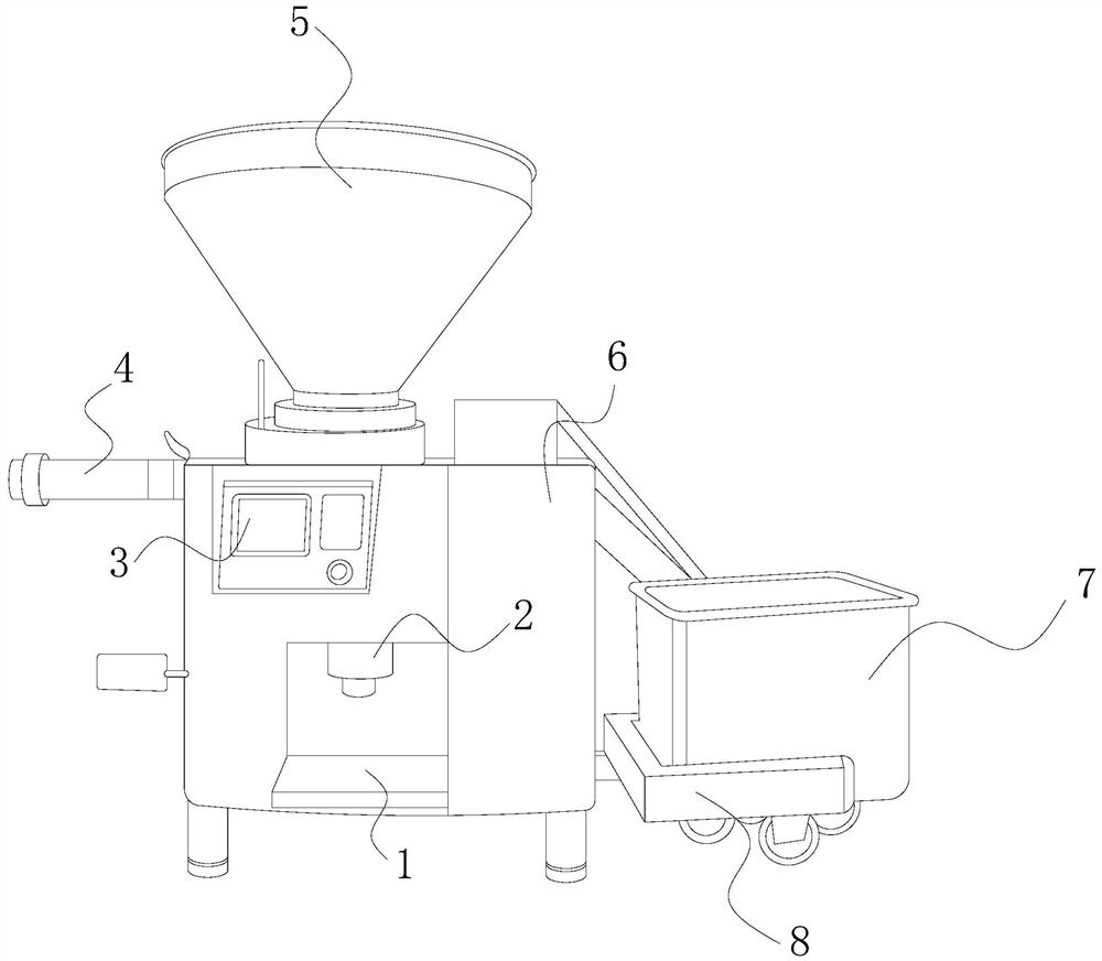
[0033] see figure 1 , the present invention provides a technical solution: a valve bag vacuum filling equipment, the structure of which includes a filling table 1, a protective device 2, a control panel 3, an evacuation valve 4, a hopper 5, a main body 6, a placement chamber 7, and a card holder 8. The filling station 1 is set at the bottom of the main body 6, the top of the filling station 1 is facing the protective device 2, and the protective device 2 is vertically inserted inside the main body 6, and the protective device 2 is connected to the hopper through the main body 6 5, the control panel 3 is installed on one side of the main body 6, the control panel 3 is embedded on the main body 6, the control panel 3 is electrically connected to the inside of the main body 6 through cables, and the top of the main body 6 is provided with There is a hopper 5, the hopper 5 is vertically embedded in the main body 6, the evacuation valve 4 and the card frame 8 are respectively inst...

Embodiment 2

[0045] see figure 1 , the present invention provides a technical solution: a valve bag vacuum filling equipment, the structure of which includes a filling table 1, a protective device 2, a control panel 3, an evacuation valve 4, a hopper 5, a main body 6, a placement chamber 7, and a card holder 8. The filling station 1 is set at the bottom of the main body 6, the top of the filling station 1 is facing the protective device 2, and the protective device 2 is vertically inserted inside the main body 6, and the protective device 2 is connected to the hopper through the main body 6 5, the control panel 3 is installed on one side of the main body 6, the control panel 3 is embedded on the main body 6, the control panel 3 is electrically connected to the inside of the main body 6 through cables, and the top of the main body 6 is provided with There is a hopper 5, the hopper 5 is vertically embedded in the main body 6, the evacuation valve 4 and the card frame 8 are respectively inst...


PUM


Abstract

The invention discloses a valve bag vacuum filling equipment, the structure of which includes a filling table, a protective device, a control panel, an evacuation valve, a hopper, a main body, a placement cavity, and a card holder. Cooperate with the wave guard to open the dust cover to the outside, which is convenient for valve pocket filling. When the filling is completed, the winding reel drives the wave guard to retract the dust cover to the inside. The dust cover is pulled inward, so that the dust cover fits on both sides of the filling head to protect the filling head and ensure the purity and quality of the beverage filling; when the beverage enters the diversion tank, the impact bullet The block blocks the filled beverage to reduce the impact of the beverage. The buffered beverage flows into the swirl plate through the impact bullet. , to prevent beverages from spilling and falling on the ground, and improve the filling efficiency of beverages.

Description

technical field [0001] The invention relates to the field of filling machinery, in particular to a valve pocket vacuum filling equipment. Background technique [0002] The filling machine can be divided into self-weight type and vacuum type according to the filling method. Self-gravity filling is to pour raw materials into the container to be filled by fluid gravity under normal pressure; vacuum filling is to use continuous vacuum suction to pump the product into the container under the action of negative pressure, and use raw materials to pass through The injector is pumped from the material tank into the waiting filling container, and the quantitative filling is realized by adjusting the length of the injector at the container mouth, which ensures the filling accuracy and is easy to operate. When filling the valve bag, the areas that need to be improved: [0003] When filling the valve pocket, the beverage is directly passed into the valve pocket through the filling head...

Claims


Application Information

Patent Timeline
Patent Type & Authority Patents(China)
IPC IPC(8): B65B3/17B65B3/26B65H75/38B65H75/44
CPCB65B3/17B65B3/26B65H75/38B65H75/4457
Inventor 刘丽敏
Owner 郑州宝腾科技有限公司
Why Eureka
Try Eureka