Supercharge Your Innovation With Domain-Expert AI Agents!

Concrete maintenance device for hydraulic engineering construction

A technology for water conservancy projects and concrete is applied in the field of concrete curing devices for water conservancy project construction, which can solve the problems of troublesome work of concrete curing and mulching, affecting the construction period, poor surface flatness of the curing membrane, etc., so as to ensure the quality of continuous maintenance and avoid prolonging the construction period. , The effect of convenient lamination work

Active Publication Date: 2021-11-02
陈琳 +1
View PDF5 Cites 2 Cited by
  • Summary
  • Abstract
  • Description
  • Claims
  • Application Information

AI Technical Summary

Problems solved by technology

[0004] However, in the process of two people pressing the side plug of the curing film into the expansion joint with a foam block in real time, it is necessary to first move the side of the curing film to a suitable position during actual operation, so that the side of the curing film can be used when the plug is pressed. It is damaged, but this will inevitably make it inefficient and seriously affect the construction period, and because the rope is paved from top to bottom, the stability of the membrane roll itself is relatively poor, resulting in the real-time paving path of the membrane roll during the real-time paving process It is easy to deflect, not only the surface flatness of the curing film is poor after paving, which affects the efficient maintenance of the concrete surface, but also affects the real-time reserved length on both sides of the curing film, and the reserved length is just for the plug pressure of the curing film. When the lengths of the two sides are different and cannot meet the plugging pressure, in the case of manual plugging, the curing film must first be adjusted before plugging, which makes the maintenance and coating work of the canal slope concrete more troublesome, and further affects the construction period. , if after paving, use the remaining curing film roll to drive out the air from the bottom of the slope from bottom to top, although the air can be driven out, but because the curing film has been blocked in the process of covering the film from top to bottom, there will be After the air is driven out, the curing film at the hollow part of the air can be closely attached to the concrete surface, but it is not attached in a straight state. Since the plugged part of the curing film can make the air inside the curing film be driven out Then the same air can enter the curing film through here, so that during the continuous curing of the concrete, the plugged position of the curing film will continue to enter the air, which will easily lead to the hollowing of the non-tight part of the curing film again. And affected by the environmental wind, it is easy to shake and vibrate, which will affect the moisture in the curing film, and then affect the quality of continuous curing. Therefore, we propose a curing device for concrete in hydraulic engineering construction

Method used


Image

  • Concrete maintenance device for hydraulic engineering construction
  • Concrete maintenance device for hydraulic engineering construction
  • Concrete maintenance device for hydraulic engineering construction

Examples


Embodiment 1

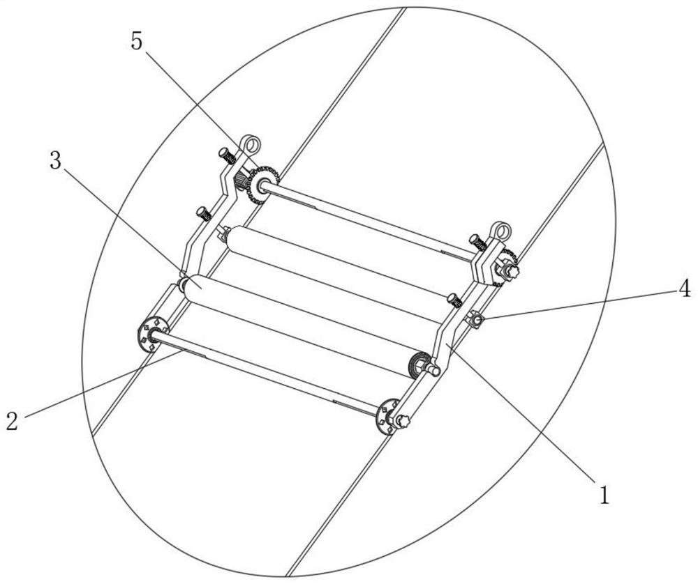
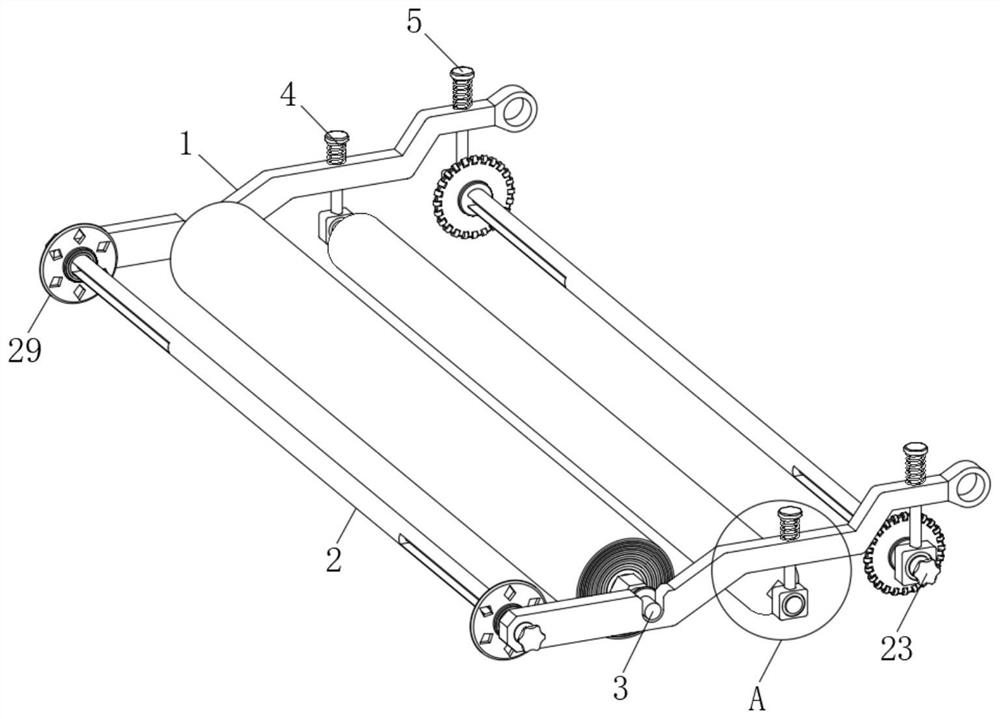
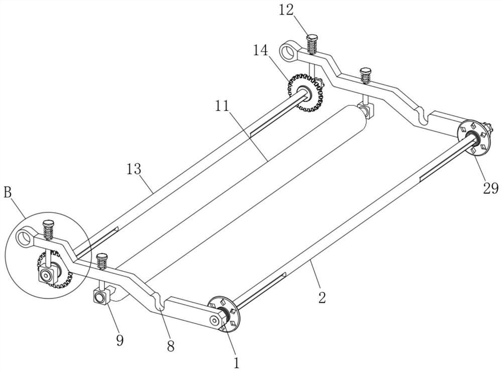
[0031] see Figure 2-10 , the present invention provides a technical solution: a maintenance device for concrete in hydraulic engineering construction, including two load-bearing side plates 1 for installation and fixing, and the load-bearing side plates 1 have a polygonal plate structure but are not limited thereto;

[0032] Between the two load-bearing side plates 1 is provided a connecting main shaft 2 installed through bearing rotation, and between the two load-bearing side plates 1 is provided a film roll fixing mechanism 3 that can be easily disassembled and assembled in real time, and the film roll The side of the fixing mechanism 3 away from the main shaft 2 is provided with a rolling mechanism 4 connected to the bearing side plates 1 on both sides for real-time paving and rolling of the maintenance film to remove air, and the rolling mechanism 4 is far away from the film roll fixing mechanism 3. One side is provided with a guide plugging mechanism 5 for cooperating wi...

Embodiment 2

[0044] see Figure 11 , the present invention provides an optimized technical solution of Embodiment 1: any end of the plug-pressing spindle 13 is connected with a drive motor 33 fixed on the mounting base, preferably the model 57HB76-401A, and during real-time use, the A mobile power supply is installed on the side bearing side plate 1 to ensure power supply and drive. Specifically, the mobile power supply can use a rechargeable lithium battery. Further, the side of the load side plate 1 away from the drive motor is fixed with a counterweight 34, and the drive motor 33 It can be used to drive and rotate the plugging spindle 13 to provide its self-rotating plugging capacity, effectively improve the real-time plugging capacity of its curing film, and ensure high-efficiency plugging. The setting of the counterweight 34 is to balance the main body of the device The weight on both sides is to ensure that it moves down the film in a stable and deflected straight line on the slope. ...


PUM


Abstract

The invention discloses a maintenance device for water conservancy construction concrete, which comprises two load-bearing side plates for mounting and fixing, a connecting main shaft installed through bearing rotation is arranged between the two load-bearing side plates, and the two load-bearing side plates There is a membrane roll fixing mechanism that can be easily disassembled and assembled in real time between the load-bearing side plates. This curing device for concrete in water conservancy construction can perform stable and efficient guiding shifts to ensure that the curing membrane is not deflected when it is paved in real time, thereby effectively ensuring maintenance. The reserved lengths at both ends of the membrane are the same. At the same time, during the real-time paving process of the curing film, it can be guaranteed that the curing film will be laid flat on the concrete surface after the curing is paved, and the curing film with the same reserved length at the side can be automatically inserted into the expansion joint. , so as to ensure high-quality film covering, to ensure subsequent high-quality maintenance, effectively facilitate the film covering work of the water channel slope concrete maintenance, ensure the film covering efficiency, effectively avoid the extension of the construction period, and ensure the concrete after film covering Continuing to maintain quality.

Description

technical field [0001] The invention relates to the technical field of slope concrete maintenance film covering, in particular to a maintenance device for concrete in hydraulic engineering construction. Background technique [0002] Concrete curing is the artificially created certain humidity and temperature conditions, so that the newly poured concrete can be normal or accelerate its hardening and strength growth. The gradual hardening and strength growth of concrete is the result of cement hydration, and the hydration of cement Certain temperature and humidity conditions are required. If such conditions do not exist in the surrounding environment, the concrete needs to be cured manually. However, in the prior art, the maintenance methods for large-area concrete are mainly realized by natural watering. During maintenance, take measures such as wrapping with molds, watering, spraying and sprinkling water to carry out moisturizing and humid maintenance to ensure that the join...

Claims


Application Information

Patent Timeline
Patent Type & Authority Patents(China)
IPC IPC(8): E02D15/02E02B5/00E02B5/02
CPCE02B5/00E02B5/02E02D15/02
Inventor 陈琳余坤
Owner 陈琳
Features
  • R&D
  • Intellectual Property
  • Life Sciences
  • Materials
  • Tech Scout
  • Unparalleled Data Quality
  • Higher Quality Content
  • 60% Fewer Hallucinations
Learn More