Missile-borne electronic product storage period acceleration test method based on multistage acceleration factors

An acceleration factor and accelerated test technology, which is applied in the direction of measuring electricity, measuring electrical variables, environment/reliability testing, etc., can solve the problem of poor verification effect during the storage period of weaponry electronic products, inability to trigger product failures, and inability to respond to weaponry activation Can wait for the problem, to achieve the effect of accurate verification results

Active Publication Date: 2020-11-03
CHINA AEROSPACE STANDARDIZATION INST
View PDF10 Cites 3 Cited by
  • Summary
  • Abstract
  • Description
  • Claims
  • Application Information

AI Technical Summary

Problems solved by technology

[0003] At present, the calculation of the test time generally involves the calculation of the activation energy. The existing methods for determining the activation energy generally use the activation energy of the weakest component or directly use a fixed value to replace the activation energy of the product. This method cannot reflect the entire The overall activation energy of weapons and equipment often leads to low calculation accuracy of test time
[0004] Moreover, the existing test time determination process often uses the first-level stress for calculation, and for many weapons and equipment, the first-level stress often cannot stimulate product failures, and the test time determined thus leads to ineffective verification of the storage period of weaponry electronic products. good

Method used


Image

  • Missile-borne electronic product storage period acceleration test method based on multistage acceleration factors
  • Missile-borne electronic product storage period acceleration test method based on multistage acceleration factors
  • Missile-borne electronic product storage period acceleration test method based on multistage acceleration factors

Examples


Embodiment Construction

[0029] The present invention will be described in detail below with reference to the accompanying drawings and examples.

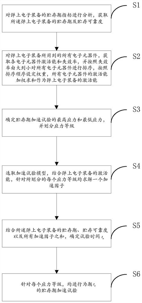
[0030] The invention provides an accelerated test method for the storage period of the electronic product on the bomb based on the multi-level acceleration factor, and its flow process is as follows figure 1 shown, including the following steps:

[0031] S1. Analyze the storage period index of the electronic equipment on the missile, and obtain the storage period and storage reliability of the electronic equipment on the missile; firstly, analyze the storage period index of the weapon equipment, and obtain the storage period and the corresponding The period is generally expressed by time t, and the unit is hour, and the storage reliability is generally expressed by γ, which is dimensionless.

[0032] S2. Obtain the activation energy and failure rate of each electronic component for all the electronic components used in the electronic equipment on the bomb...


PUM


Abstract

The invention discloses a missile-borne electronic product storage period acceleration test method based on multistage acceleration factors, which can calculate the test time more in line with the real storage period of weapon equipment electronic products, so the verification result is more accurate. The method specifically comprises the steps: acquiring the storage period and the storage reliability of the missile-borne electronic equipment; acquiring activation energy and failure rates of all electronic components of the missile-borne electronic equipment, sorting according to a descendingorder of the failure rates, setting a weight, and performing weighted summation on the activation energy of all the electronic components to serve as the activation energy of the missile-borne electronic equipment; determining the highest stress and the lowest stress of the accelerated test in the storage period, and dividing stress grades; selecting an acceleration test model, and solving an acceleration factor for each divided stress level in combination with the activation energy of the missile-borne electronic equipment; determining the test time ta in combination with the storage period and the storage reliability of the missile-borne electronic equipment and the sum of all acceleration factors; for each stress grade, carrying out a storage period acceleration test for a period ta.

Description

technical field [0001] The invention relates to the technical field of aerospace reliability testing, in particular to a method for accelerating the storage period of electronic products on missiles based on multi-level acceleration factors. Background technique [0002] Missile weapons and equipment are "long-term storage, one-time use" products. The storage period refers to the storage time that meets the specified storage reliability requirements under specified storage conditions. It is one of the important technical indicators of missile weapons. Validation of shelf life is required. For the verification of the storage period, it is generally verified by the accelerated test method, and the test time needs to be calculated in advance during the test process. [0003] At present, the calculation of the test time generally involves the calculation of the activation energy. The existing methods for determining the activation energy generally use the activation energy of t...

Claims


Application Information

Patent Timeline
Patent Type & Authority Applications(China)
IPC IPC(8): G01R31/00
CPCG01R31/003Y02D10/00
Inventor 徐洪武陈凤熹朱炜王喜奎韩天龙王伟蔡健平施帆伍招冲张睿宋汝宁张晓军
Owner CHINA AEROSPACE STANDARDIZATION INST
Why Eureka
Try Eureka