Methods for attaching connective tissues to bone using a multi-component anchor

a multi-component, anchoring technology, applied in the field of anchoring methods and methods for attaching connective tissue, can solve the problems of increasing the difficulty of articular joint flexion, pain and loss of the ability to elevate and externally rotate the arm, residual weakness, etc., to achieve the effect of reducing failure rates, concentrating stress, and facilitating operation

Inactive Publication Date: 2008-01-17
ARTHROCARE
View PDF99 Cites 52 Cited by
  • Summary
  • Abstract
  • Description
  • Claims
  • Application Information

AI Technical Summary

Benefits of technology

[0011] The present invention solves the problems outlined above by providing an innovative bone anchor and connective techniques which permit a suture attachment which lies entirely beneath the cortical bone surface, and wherein the suturing material between the connective tissue and the bone anchor is oriented in a direction generally transverse to the longitudinal axis of the bone anchor, so that axial pull-out forces exerted on the bone anchor are minimized. The suture attachment to the bone anchor involves the looping of a substantial length of suturing material around a shaft of the anchor, thereby avoiding an eyelet connection which requires a knot and which concentrates stress on a very small portion of the suturing material. Thus, failure rates are greatly decreased over conventional techniques, and the inventive procedures are significantly easier to perform than conventional techniques.
[0015] Importantly, the suturing material joining the tissue to the anchoring mechanism lies in a direction generally transverse to that of a longitudinal axis of the anchoring mechanism. This permits the inventive mechanism to be subjected to little or no axial “pull-out” forces, due to the attachment of the anchoring mechanism to the torn connective tissue, such as a tendon, relative to prior art suture anchors of this type, thereby sharply reducing the chance of failure of the anchoring mechanism because of its inadvertent separation from the bone.

Problems solved by technology

It is an increasingly common problem for tendons and other soft, connective tissues to tear or to detach from associated bone.
One such type of tear or detachment is a “rotator cuff” tear, wherein the supraspinatus tendon separates from the humerus, causing pain and loss of ability to elevate and externally rotate the arm.
Because of this maneuver, the deltoid requires postoperative protection, thus retarding rehabilitation and possibly resulting in residual weakness.
Although the above described surgical technique is the current standard of care for rotator cuff repair, it is associated with a great deal of patient discomfort and a lengthy recovery time, ranging from at least four months to one year or more.
It is the above described manipulation of the deltoid muscle together with the large skin incision that causes the majority of patient discomfort and an increased recovery time.
Unfortunately, the skill level required to facilitate an entirely arthroscopic repair of the rotator cuff is inordinately high.
Intracorporeal suturing is clumsy and time consuming, and only the simplest stitch patterns can be utilized.
Extracorporeal knot tying is less difficult, but their tightness cannot later be adjusted.
Knots tied arthroscopically are difficult to achieve, impossible to adjust, and are located in less than optimal areas of the shoulder.
Suture tension is also impossible to measure and adjust once the knot has been tied.
Consequently, because of the technical difficulty of the procedure, presently less than 1% of all rotator cuff procedures are of the arthroscopic type, and are considered investigational in nature.
A significant difficulty with current arthroscopic rotator cuff repair techniques are shortcomings related to currently available suture anchors.
Suture eyelets in bone anchors available today are small in radius, and can cause the suture to fail at that location when the anchor is placed under high tensile loads.
This presents a problem because of the limited bone space available for the insertion of bone anchors.
The need to utilize additional bone anchors to satisfactorily complete a procedure, leaving extra useless anchors in the bone, can severely compromise the ability to perform subsequent procedures, should they be required.
Furthermore, due to design, some anchors are limited in the way that they can be placed into the bone.
For example, two Mitek anchors must not be placed too near one another or too near the edge of a bone as the “retention barbs” present on anchors of this particular design would interfere with each other or fall outside the surface of the bone.
A major problem with existing suture anchor designs is the location of the suture attachment point (typically an eyelet) at the exposed proximal end of the anchor.
As a consequence, if the suturing material itself does not break at the point of attachment, as discussed supra, then there is still a substantial risk that the bone anchor will pull out of the bone, causing the connective tissue to once again become at least partially detached from the bone.
If either suture failure or anchor pull-out occurs after the surgical procedure has been completed, then an entirely new repair procedure must be initiated, with its attendant costs, discomfort, inconvenience, and rehabilitation.
Other methods of securing soft tissue to bone are known in the prior art, such as staples and tacks, but are not presently considered to be feasible for shoulder repair procedures, because of physicians' reluctance to leave anything but a suture in the capsule area of the shoulder.
The reason for this is that staples, tacks, and the like could possibly fall out and cause injury during movement.
Screws are also known for such attachment procedures, but suffer from a number of disadvantages, including their tendency to loosen over time, requiring a second procedure to later remove them, and their requirement for a relatively flat attachment geometry.

Method used


Image

  • Methods for attaching connective tissues to bone using a multi-component anchor
  • Methods for attaching connective tissues to bone using a multi-component anchor
  • Methods for attaching connective tissues to bone using a multi-component anchor

Examples


Embodiment Construction

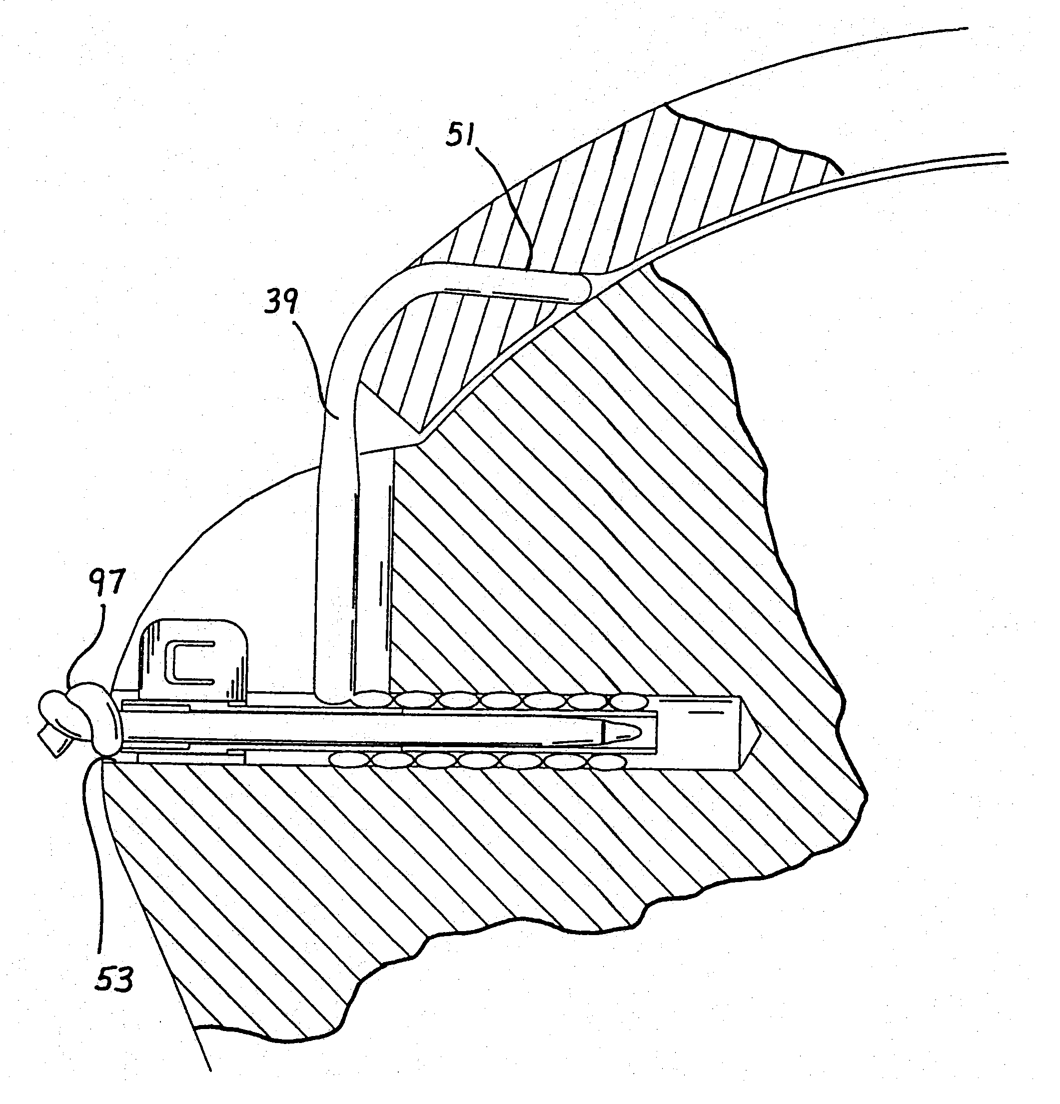
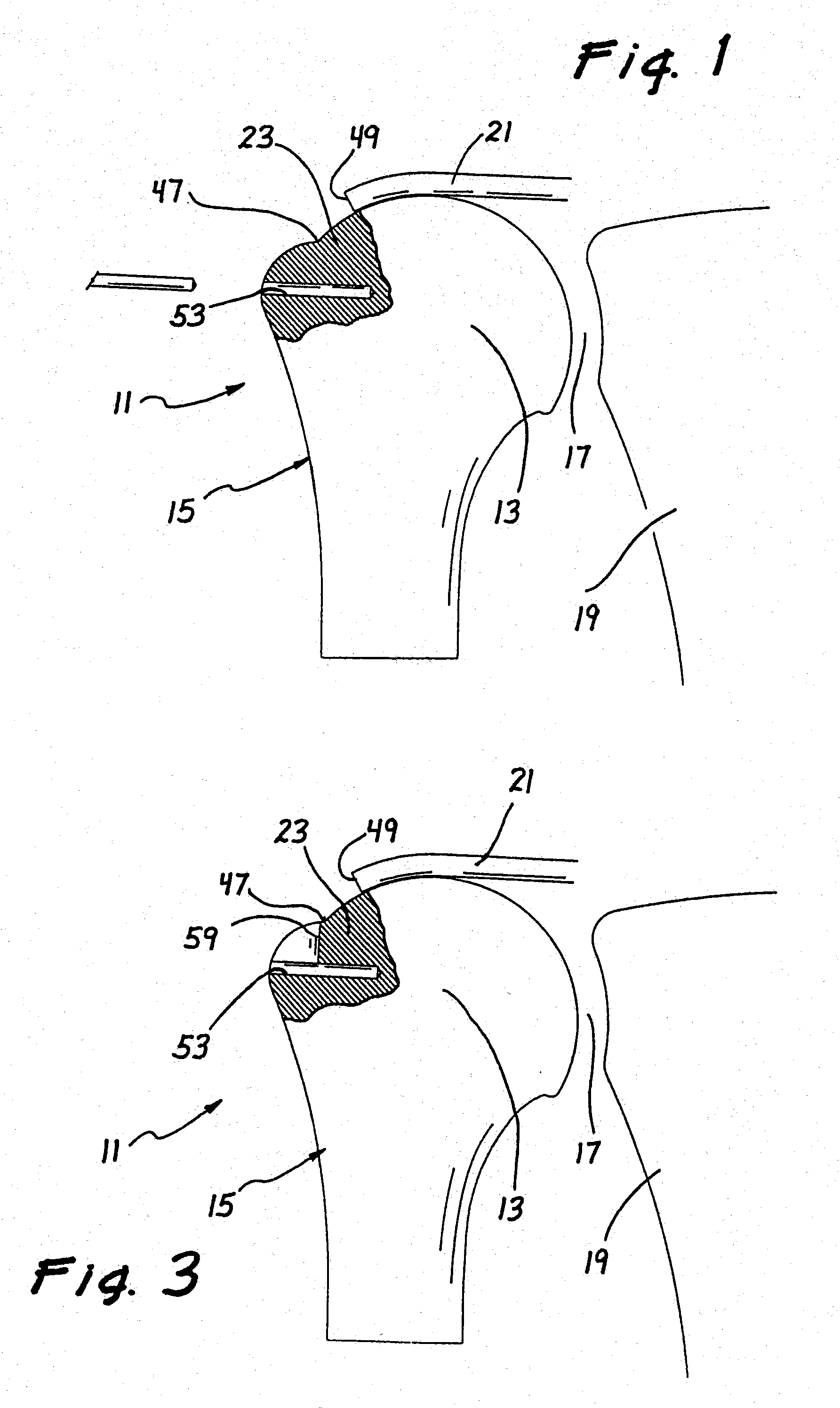
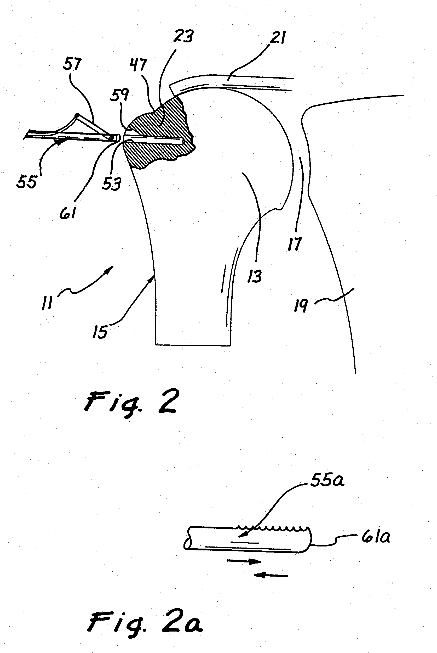
[0060] Referring now more particularly to the drawings, there is shown in FIG. 1 a portion of a partially torn rotator cuff 11. In the illustration, which is simplified for purposes of clarity, a globular head 13 of a humerus 15 is disposed in a glenoid cavity 17 formed by a scapula 19. A supraspinatus tendon 21, the end of which is normally fully attached onto a facet of a greater tuberosity 23, is shown in a detached condition, resulting in a diagnosis that the rotator cuff has been torn.

[0061] Now with particular reference to FIGS. 7 and 8, there is illustrated one preferred embodiment of a knotless suture anchoring device 25 constructed in accordance with the principles of the invention. In its preferred configuration, the anchoring device 25 comprises a hollow stem or shaft 27, having a longitudinal axis 28 and a periphery. A pair of longitudinal slits 29 extend along a portion of a distal section of the shaft 27 from its distal end 31, and a wider and shorter recess 32 may al...


PUM


Abstract

An innovative bone anchor and methods for securing connective tissue, such as tendons, to bone are disclosed which permit a suture attachment which lies entirely beneath the cortical bone surface, and wherein the suturing material between the connective tissue and the bone anchor is oriented in a direction generally transverse to the longitudinal axis of the bone anchor, so that axial pull-out forces exerted on the bone anchor are minimized. The suture attachment to the bone anchor involves the looping of a substantial length of suturing material around a shaft of the anchor, thereby avoiding an eyelet connection which requires a knot and which concentrates stress on a very small portion of the suturing material. Thus, failure rates are greatly decreased over conventional techniques, and the inventive procedures are significantly easier to perform than conventional techniques.

Description

BACKGROUND OF THE INVENTION [0001] This invention relates generally to methods and apparatus for attaching soft tissue to bone, and more particularly to anchors and methods for securing connective tissue, such as ligaments or tendons, to bone. The invention has particular application to arthroscopic surgical techniques for reattaching the rotator cuff to the humeral head, in order to repair the rotator cuff. [0002] It is an increasingly common problem for tendons and other soft, connective tissues to tear or to detach from associated bone. One such type of tear or detachment is a “rotator cuff” tear, wherein the supraspinatus tendon separates from the humerus, causing pain and loss of ability to elevate and externally rotate the arm. Complete separation can occur if the shoulder is subjected to gross trauma, but typically, the tear begins as a small lesion, especially in older patients. [0003] To repair a torn rotator cuff, the typical course today is to do so surgically, through a ...

Claims


Application Information

Patent Timeline
Patent Type & Authority Applications(United States)
IPC IPC(8): A61B17/56A61B17/04A61F2/08
CPCA61B17/0401A61B2017/0409A61B2017/0414A61B2017/0458A61F2002/0888A61F2/0811A61F2002/0829A61F2002/0858A61F2/0805
Inventor RITCHART, MARK A.FOERSTER, SETH A.
Owner ARTHROCARE
Why Eureka
Try Eureka