
Switch control circuit and power supply equipment

A technology of switch control circuit and switch tube, which is applied in the control/regulation system, electrical components, regulating electrical variables, etc., can solve the problems of device damage such as switch tube, mis-connection of switch tube, etc., to prevent false turn-on and promote fast turn-off interruption, increased flexibility and safety

Pending Publication Date: 2020-11-03
深圳市爱达思技术有限公司
View PDF0 Cites 2 Cited by
  • Summary
  • Abstract
  • Description
  • Claims
  • Application Information

AI Technical Summary

Problems solved by technology

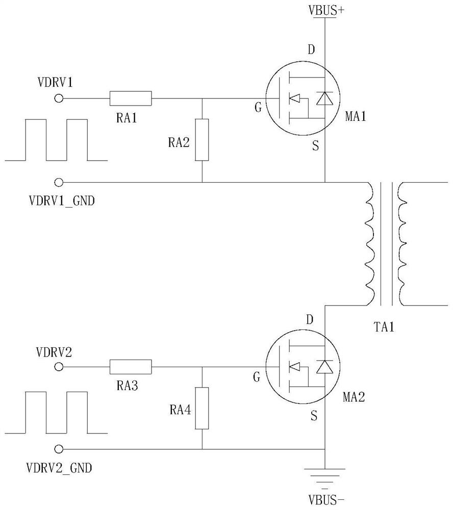
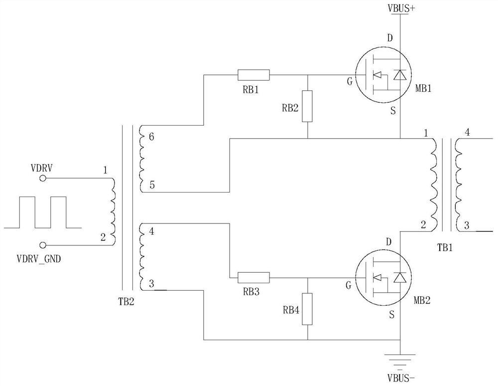
[0004] The embodiment of the present application provides a switch control circuit and power supply equipment, which can solve the problem that the switch tube in the gate drive circuit is disturbed and causes false conduction, which leads to damage to the switch tube and other devices

Method used


Image

  • Switch control circuit and power supply equipment
  • Switch control circuit and power supply equipment
  • Switch control circuit and power supply equipment

Examples


Embodiment Construction

[0034] In the following description, specific details such as specific system structures and technologies are presented for the purpose of illustration rather than limitation, so as to thoroughly understand the embodiments of the present application. It will be apparent, however, to one skilled in the art that the present application may be practiced in other embodiments without these specific details. In other instances, detailed descriptions of well-known systems, devices, circuits, and methods are omitted so as not to obscure the description of the present application with unnecessary detail.

[0035] It should be understood that when used in this specification and the appended claims, the term "comprising" indicates the presence of described features, integers, steps, operations, elements and / or components, but does not exclude one or more other Presence or addition of features, wholes, steps, operations, elements, components and / or collections thereof.

[0036] It should...


PUM


Abstract

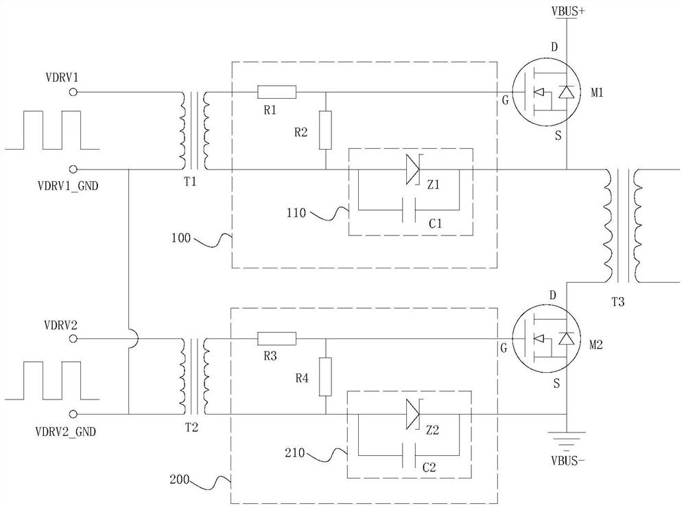
The invention is applicable to the technical field of power electronics, and provides a switch control circuit and power supply equipment, which comprises a first switch tube, a second switch tube, afirst pulse transformer, a second pulse transformer, a first driving circuit and a second driving circuit. In the switch control circuit, the two pulse transformers and the two drive circuits are adopted to drive the two switch tubes respectively, and the flexibility and safety of switch tube control can be improved. When the switch control circuit works in a non-power conversion state in real time, the drive circuit presets negative voltage to the control end of the switch tube, and it is guaranteed that the switch tube maintains a reliable turn-off state. When the switch control circuit works in a power conversion state, the drive circuit applies a set pulse signal to the control end of the switch tube, it is guaranteed that the drive voltage of the switch tube is negative in the turn-off process, so that rapid turn-off of the switch tube is promoted, and misconduction, caused by the miller effect, of the switch tube is effectively prevented.

Description

technical field [0001] The application belongs to the technical field of power electronics, and in particular relates to a switch control circuit and power supply equipment. Background technique [0002] Semiconductor power switch tube is an important core device in power electronic products, and its working status determines the key performance indicators of the product. The working state of the power switch tube is determined by its gate drive circuit. The requirements for the gate drive circuit are: when the drive switch tube is turned on, the on-resistance is formed as small as possible, and when it is turned off, the open-circuit resistance is formed as large as possible, in order to achieve ideal switching characteristics. However, due to the limitations of the physical characteristics of semiconductors and the structure of the gate drive circuit of the switch, in fact, it is impossible for the power switch to achieve ideal switching characteristics. Since the physica...

Claims


Application Information

Patent Timeline
Patent Type & Authority Applications(China)
IPC IPC(8): H02M1/088H02M3/335
CPCH02M1/088H02M3/33569
Inventor 郑兵江凡
Owner 深圳市爱达思技术有限公司
Learn More