
Electromagnetic proportional valve and system having a proportional valve

An electromagnetic proportional valve and armature technology, applied in the direction of batteries, circuits, electrical components, etc., can solve the problems of complex proportional valve structure, complicated proportional valve function interference, and inability to manufacture proportional valves.

Active Publication Date: 2021-07-30
ECO HLDG 1 GMBH
View PDF4 Cites 0 Cited by
  • Summary
  • Abstract
  • Description
  • Claims
  • Application Information

AI Technical Summary

Problems solved by technology

[0003] However, the construction of the known proportional valves is very complex, so that the proportional valves cannot be produced simply and cost-effectively
In addition, the increased complexity often leads to disturbances in the individual functions of the proportional valves

Method used


Image

  • Electromagnetic proportional valve and system having a proportional valve
  • Electromagnetic proportional valve and system having a proportional valve
  • Electromagnetic proportional valve and system having a proportional valve

Examples


Embodiment Construction

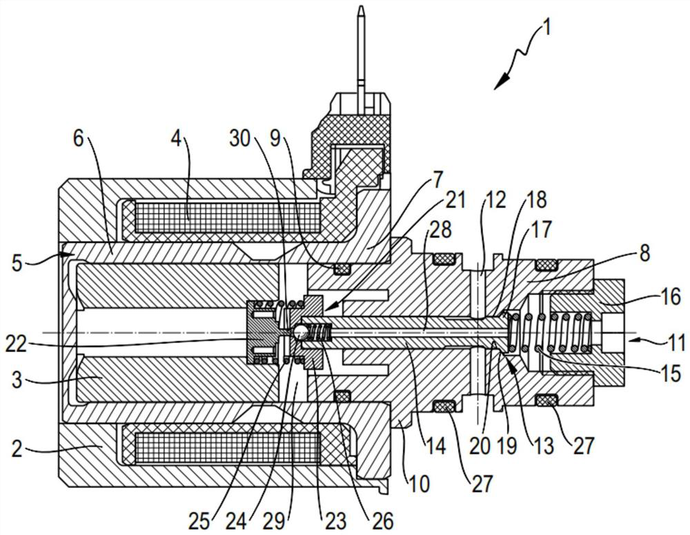
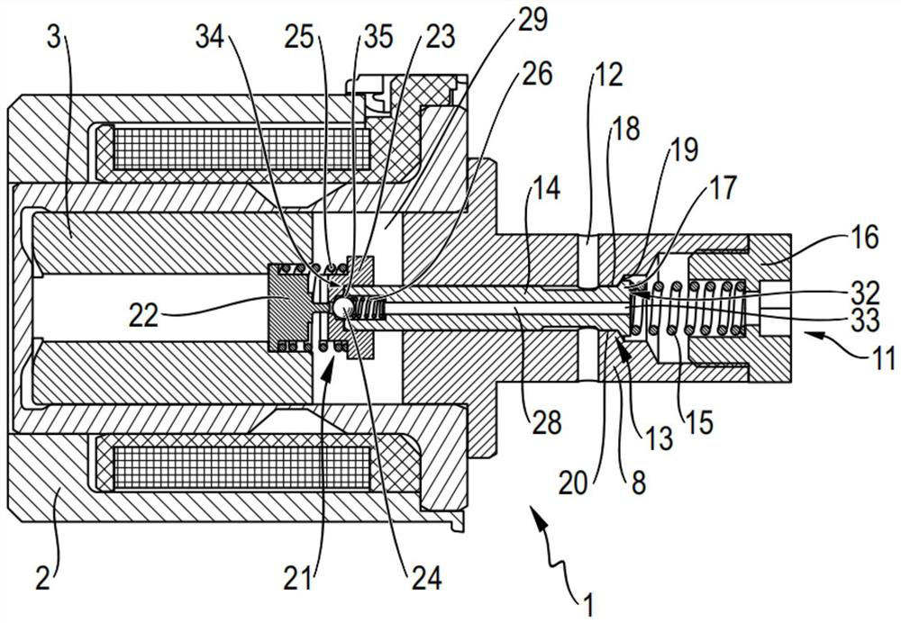
[0055] figure 2 A longitudinal sectional view of the proportional valve 1 according to the invention in the closed state is shown. Here, the closed state is a state in which the main valve device 13 is closed so that fluid cannot flow from the inlet 11 to the outlet 12 . Proportional valve 1 is also called expansion valve.

[0056] The inlet 11 and the outlet 12 are arranged in the valve sleeve 8 of the proportional valve 1 . The inlet 11 is arranged axially at the longitudinal end of the valve bushing 8 . The outlet 12 is arranged radially on the valve bush 8 .

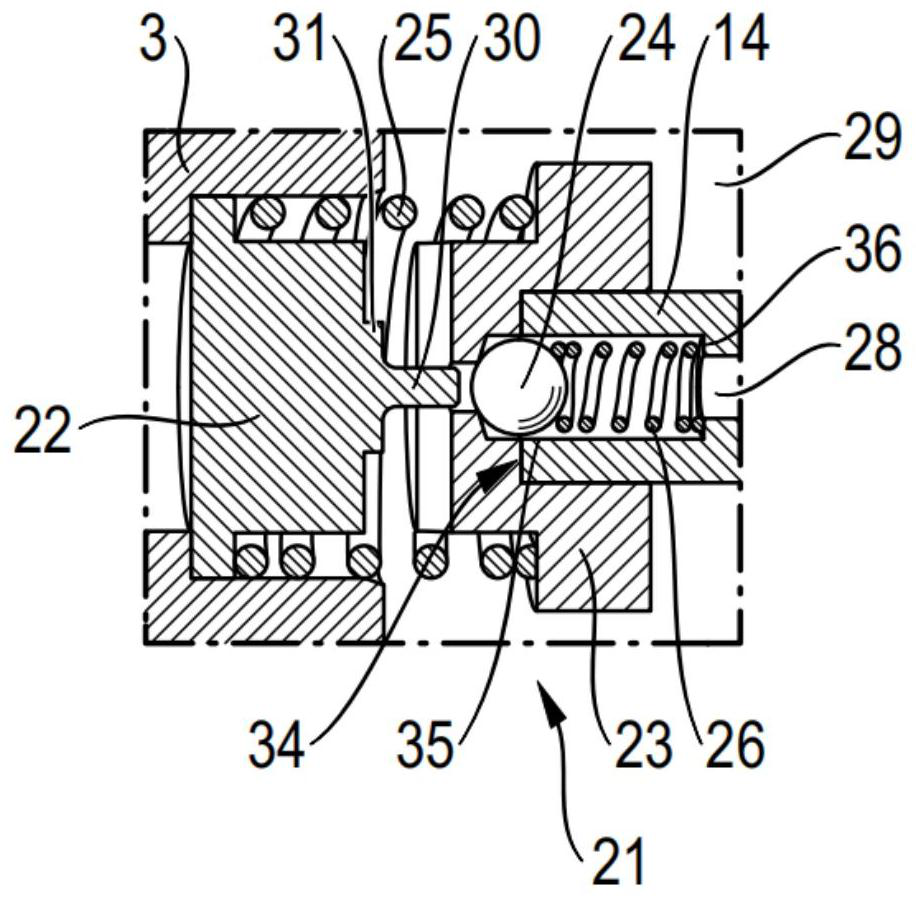
[0057] The proportional valve 1 has an electromagnet 2 and an armature 3 . Armature 3 is axially movable by means of electromagnet 2 . In particular, the armature 3 is movable towards the inlet 11 . An actuating element 22 is arranged on the armature 3 . The actuating element 22 is arranged in particular on an axial end region of the armature 3 . The actuating element 22 moves together with the armature 3 . ...


PUM


Abstract

The invention relates to an electromagnetic proportional valve (1), preferably for refrigerant, comprising the following: an armature (3) of an electromagnet (2), which is movably arranged axially between a rest position, an actuating position and working positions and on which an actuating element (22) is arranged; a piston (14), which is designed as a hollow piston and has, on a first axial end region (32), a first opening (33) toward an inflow (11) of the expansion valve (1) and has, on a second axial end region (34), a second opening (35) toward a pressure equalization chamber (29); and a blocking body (24), which is designed to close the second opening, wherein the piston (14) is axially movably arranged and wherein the piston (14) is designed to block a fluid passage as a shut-off element of a main valve device (13), wherein the fluid passage of the main valve device (13) is blocked in the rest position of the armature (3), wherein the actuating element (22) is designed to act on the blocking body (24) when the armature (3) is in the actuating position such that said blocking body exposes the second opening at least in regions, and wherein the fluid passage of the main valve device (13) is opened in the working positions of the armature (3). The invention furthermore relates to a system having such a proportional valve (1).

Description

technical field [0001] The invention relates to an electromagnetic proportional valve. Furthermore, the invention relates to a system with an electromagnetic proportional valve. Background technique [0002] Valves are commonly used to block and / or control the flow of fluids. Simpler valves are only discretely controllable. This means that they can only be switched on / off (auf / zu), ie can only be opened and closed. However, simple opening and closing of the valve is no longer sufficient for many applications. For example, expansion valves used in battery cooling, air conditioning, or heat pump systems to create a defined and controlled pressure drop there between the condenser (heat release) and evaporator (cooling), such use usually requires a more continuous switch. Overall, therefore, continuous switching is often required. Such a continuous or continuous switching can be realized, for example, by means of a proportional valve which allows a continuous transition of...

Claims


Application Information

Patent Timeline
Patent Type & Authority Applications(China)
IPC IPC(8): F25B41/34
CPCH01M10/613Y02B30/70Y02E60/10H01M10/625B60H1/00485F25B41/34F25B2341/067F25B41/345H01M10/6569B60H2001/3286H01M2220/20
Inventor T·施奈德D·雷曼J·莫林
Owner ECO HLDG 1 GMBH
Learn More