[0026] Example
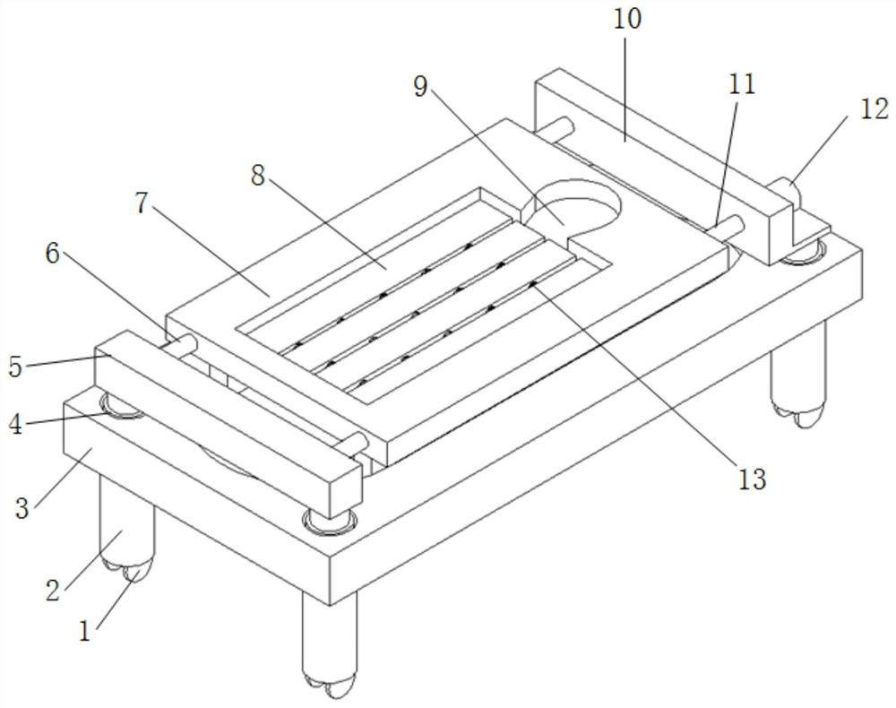
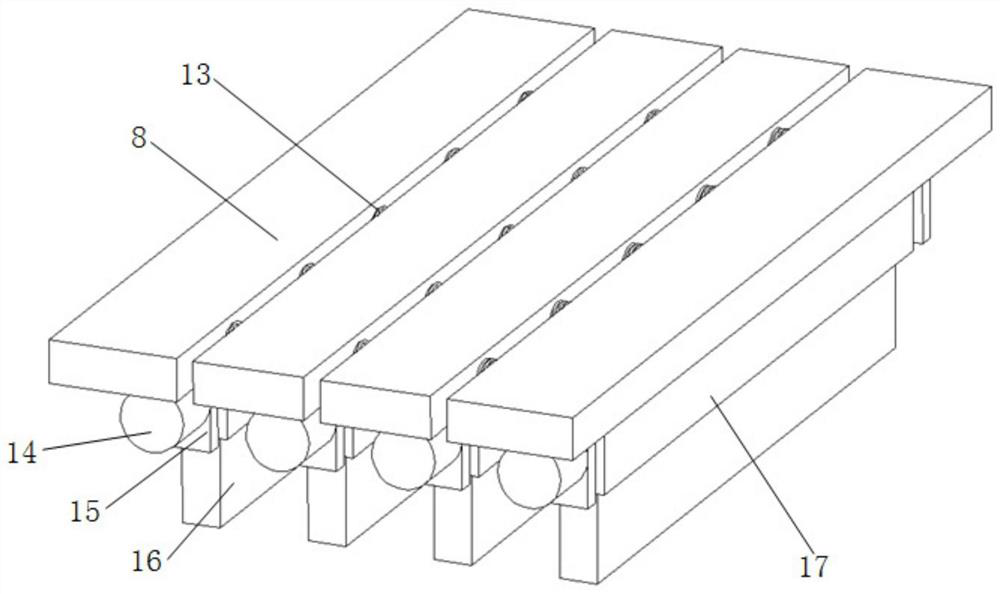
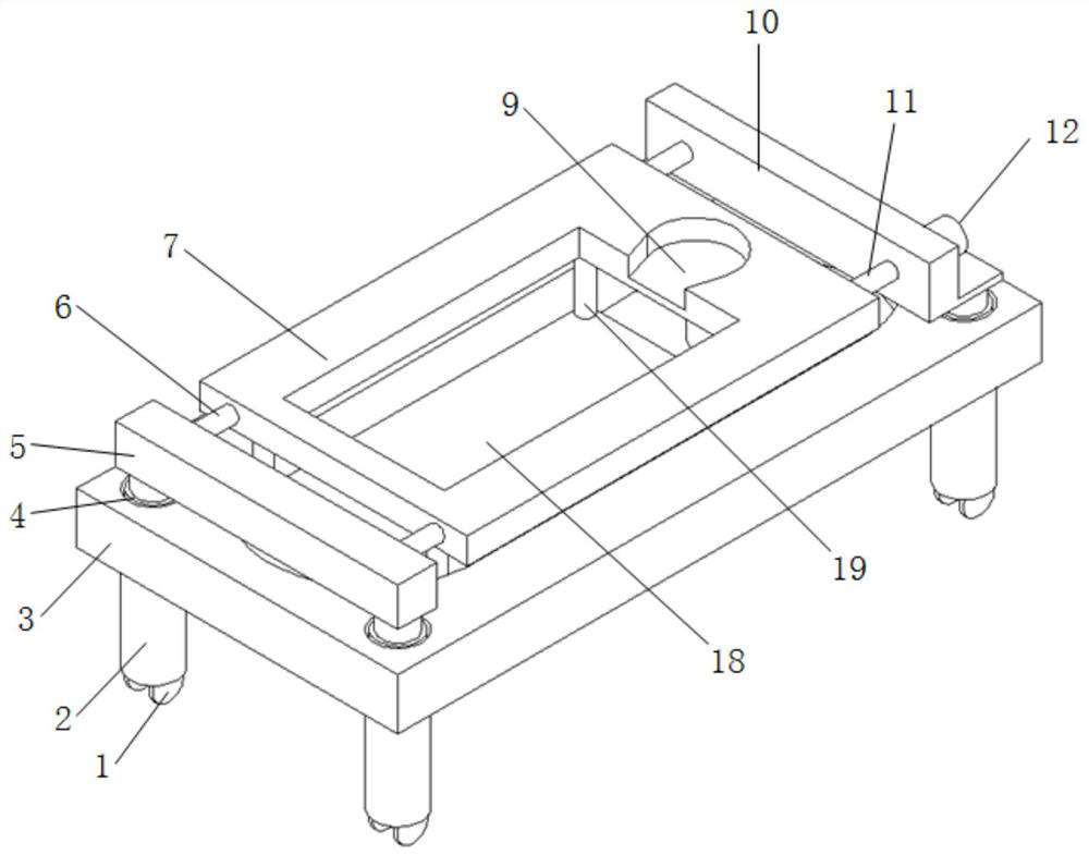
[0027] An auxiliary fixation frame for tumor radiotherapy, such as Figure 1-4 As shown, it includes a fixed plate 3, a limit device and an attitude adjustment device;
[0028] The four corners of the bottom of the fixed plate 3 are fixedly provided with support columns 2, and the bottom of each support column 2 is provided with a telescopic universal wheel 1, and when it is necessary to move, the universal wheel 1 is stretched out of the support column 2. When the treatment is used, Retract the universal wheel 1 to the support column 2 to avoid movement or shaking during use, such as Figure 4 As shown; the four corners of the top of the fixed plate 3 are provided with circular grooves, and each circular groove is provided with a first hydraulic cylinder 4, which is used to raise and lower the height of the entire limit device, and adjust it according to the treatment goal; fixed A connecting plate 5 and an L-shaped frame plate 10 are respectively arranged above the two ends of the plate 3, and the connecting plate 5 and the L-shaped frame plate 10 are respectively fixedly connected with the push rod ends of the first hydraulic cylinder 4 at both ends;
[0029] Limiting device comprises support plate 18 and middle part offers the limit plate 7 that is provided with square through groove, as image 3 Shown; Support plate 18 is erected below the square through groove by the electric telescoping rod 19 of four corners, adopts electric telescoping rod 19 to be convenient to the whole height of adjustment posture adjusting device; Fixed plate 3 offers the through groove that cooperates with support plate 18, avoids contact with The support plate 18 produces interference problems; the limit plate 7 is erected between the connecting plate 5 and the L-shaped frame plate 10, and is driven to move by the first driving device; the position is fine-tuned through the driving and moving of the first driving device, which is convenient for adjusting the position during treatment ;
[0030] The posture adjusting device comprises several rotating plates 8 and rotating devices, such as figure 2 As shown; the top of the support plate 18 is uniformly provided with several connection blocks 16, and the top of each connection block 16 is fixedly provided with a support block 17, and each rotating plate 8 is rotatably connected with a support block 17, and is driven by a rotating device Rotation; by rotating the rotating plate 8, the angle of the entire plate surface can be adjusted, thereby assisting the patient to turn over or passively change the lying position;
[0031] The sides of two adjacent rotating plates 8 are connected by several limit springs 13, which limit the positions of the two rotating plates 8 and avoid deformation of the rotating plates 8 or mutual position changes due to pressure; several rotating plates 8 form a plane, cooperate with the square through groove.
[0032] Further, the first driving device includes a first motor 12, a lead screw 11 and a polished rod 6, such as image 3 As shown; the first motor 12 is fixedly arranged on one side of the L-shaped frame plate 10, the output shaft of the first motor 12 passes through the L-shaped frame plate 10, and is connected with one end of the lead screw 11; the other end of the lead screw 11 Through the limiting plate 7, and connected with the connecting plate 5 in rotation, the lead screw 11 is threadedly matched with the limiting plate 7; It is rotatably connected with the connecting plate 5 and the L-shaped frame plate 10. Through the driving mode of the screw slider, the horizontal movement of the whole limiting plate 7 and the device connected with the limiting plate 7 is realized.
[0033] Preferably, the rotating device includes a rotating shaft, a second motor 14 and two motor plates 15; the two ends of the bottom of the rotating plate 8 are respectively fixedly provided with motor plates 15, and the second motor 14 is fixedly arranged on the outside of one motor plate 15. The output shaft of the two motors 14 passes through the motor plate 15 and is connected to one end of the rotating shaft; the rotating shaft passes through the supporting block 17 and is fixedly connected to the supporting block 17; When the second motor 14 rotates, the rotating plate 8 is driven to rotate, and the auxiliary adjustment of the posture is realized by changing the angle of the rotating plate 8;
[0034] Furthermore, a second hydraulic cylinder is embedded in the bottom of each connecting block 16, and the end of the push rod of the second hydraulic cylinder is fixedly connected with the support block 17, so that the height of each rotating plate 8 can be adjusted, and multiple rotating plates 8 can By fitting it is adjusted to an incline that assists in posture adjustment.
[0035] Preferably, the bottom of the support column 2 is provided with a cylindrical groove that cooperates with the universal wheel 1, and the third hydraulic cylinder 20 is arranged in the cylindrical groove, and the end of the push rod of the third hydraulic cylinder 20 is provided with the universal wheel 1, which is convenient for universal The expansion and contraction of the wheel 1 in the support column 2.
[0036] In addition, one end of the square through groove of the limiting plate 7 is provided with a head support groove 9 for placing the head and limiting the position of the head.
[0037] In this example,
[0038] Move the device under the radiation therapy device, and the patient lies on several rotating plates 8 in the middle of the limiting plate 7, and adjusts the overall height of the rotating plates 8 by driving four sets of electric telescopic rods 19 to a more comfortable position;
[0039] When it is necessary to move the whole device, drive the third hydraulic cylinder 20 to extend, extend the universal wheel 1 from the support column 2, and move through the universal wheel 1; during treatment, drive the third hydraulic cylinder 20 to contract, and extend the universal wheel 1 The wheel 1 is received in the hole of the support column 2, and the support of the whole device is realized through the four support columns 2;
[0040]Adjust the position of the affected part: drive the first motor 12 to rotate, drive the lead screw 11 to rotate, and then drive the limit plate 7 threaded with the lead screw 11 to move, realizing the forward and backward movement of the affected part; by driving the expansion and contraction of the first hydraulic cylinder 4, to adjust the height of the affected part;
[0041] Adjust the patient's posture: by driving the second motor 14 at the bottom of each rotating plate 8, the entire rotating plate 8 can be rotated, and the height adjustment of the rotating plate 8 can be realized by driving the second hydraulic cylinder, so that the patient can lie on both sides of the plane The rotating plate 8 rotates and rises to form slopes with different angles, which is convenient for patients to turn over and lie on their side, and assists in the adjustment of posture; through the limitation of several limit springs 13, a plane composed of multiple rotating plates 8 is added Strength of.