High-altitude projection fire extinguishing equipment

A technology of fire extinguishing equipment and hot air balloon, which is applied in fire rescue and other fields, and can solve the problems of small impact on the ground, affecting fire extinguishing efficiency, and scattering of sand and soil, and achieves high fire extinguishing efficiency

Active Publication Date: 2020-11-06
NANAN RONGHUA MECHANICAL TECH CO LTD
View PDF5 Cites 0 Cited by
  • Summary
  • Abstract
  • Description
  • Claims
  • Application Information

AI Technical Summary

Problems solved by technology

However, this forest fire-fighting robot throws the sand from the ground to the fire place, and the trajectory of the sand in the air is parabolic. It is located at the highest position where the sand is projected, and has no direct relationship with the projectile force. The impact force on the ground is relatively small, and the sand is easy to disperse under the action of obstacles such as branches, which affects the fire extinguishing efficiency.

Method used


Image

  • High-altitude projection fire extinguishing equipment
  • High-altitude projection fire extinguishing equipment

Examples


Embodiment 1

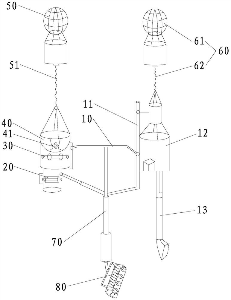
[0033] Such as figure 1 As shown, this embodiment provides a high-altitude projectile fire extinguishing equipment, including a bracket 10, a projectile device 20 fixedly connected to the support 10, a crushing device 30 located above the projectile device 20 and connected to the feed port of the projectile device 20, located at The feeding box 40 above the crushing device 30 and connected to the feed port of the crushing device 30, the first hot air balloon 50 above the feeding box 40, and the first stay rope connected between the first hot air balloon 50 and the support 10 51, wherein, the material inlets of each of the above devices are located at the upper end of the corresponding device, and the material outlets are located at the lower end of the corresponding device, and each device is fixedly connected to the bracket 10 respectively. The discharge port of the projecting device 20 is arranged vertically downward or inclined downward relative to the horizontal plane. In ...

Embodiment 2

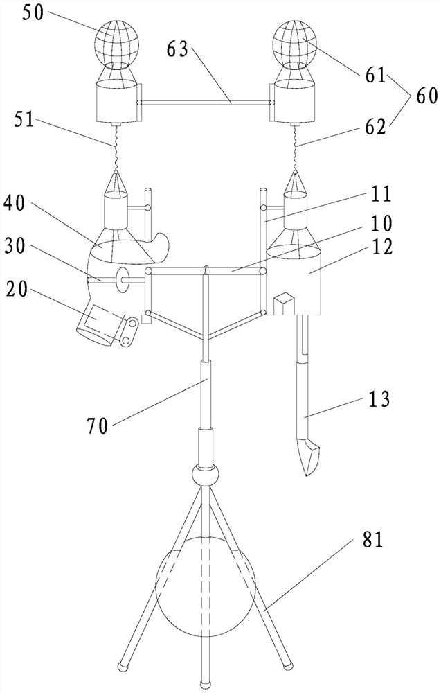
[0041] Such as figure 2 As shown, the difference between the high-altitude projectile fire extinguishing equipment provided by this embodiment and the first embodiment is that this embodiment uses a triangular support base 81 instead of a crawler-type walking chassis 80, so that the entire equipment can be directly lifted by a hot air balloon without the need Move to the fire site by walking on the ground, and the deployment speed is relatively fast.

[0042] Secondly, in this embodiment, a tie rod 63 is connected between the first hot-air balloon 50 and the second hot-air balloon 61, which facilitates the two hot-air balloons to work together.

[0043]In addition, in this embodiment, the discharge port of the projecting device 20 is vertically arranged downwards relative to the horizontal plane, and the feeding box 40 in this embodiment is not provided with a pre-crushing mechanism. At the same time, the shell of the projecting device 20, The casing of the crushing device 3...


PUM


Abstract

The invention provides high-altitude projection fire extinguishing equipment. The equipment comprises a bracket, a projection device, a crushing device positioned above the projection device and connected with a feeding port of the projection device, a feeding box positioned above the crushing device and connected with a feeding port of the crushing device, a first hot air balloon positioned abovethe feeding box and a first pull rope connected between the first hot air balloon and the bracket, wherein a discharge port of the projection device is vertically arranged downwards or obliquely arranged downwards relative to the horizontal plane. By arrangement of the first hot air balloon, the projection device can be drawn to a position right above or lateral above a fire site to project sandfrom top to bottom. The projection force needs not to overcome gravity action, and can form joint force with gravity to push the sand to move down. The grounding impact force is relatively large, barriers can be easily broken through to cover flames accurately, and strong airflow can also be formed to extinguish the surrounding flames on the basis of coverage of combustibles and prevention of combustion of the combustibles, so that fire extinguishing efficiency is relatively high.

Description

technical field [0001] The invention relates to emergency rescue equipment, in particular to high-altitude projectile fire extinguishing equipment. Background technique [0002] Projectile fire extinguishing equipment is a kind of fire extinguishing equipment that uses solid materials such as sand and soil as fire extinguishing materials, and throws them onto the fire source by means of projection to cover combustibles. Because it can be obtained locally, it is widely used in various fields such as forest fire extinguishing. In fire fighting in outdoor environments. [0003] The Chinese invention patent application with the publication number CN109731256A discloses a forest fire extinguishing robot and a method for realizing fire extinguishing by throwing soil and using local materials. The body is used to break the soil block, and the soil-breaking mechanism is provided with an outlet; the excavating mechanism is supported by the car body, and the excavating mechanism can ...

Claims


Application Information

Patent Timeline
IPC IPC(8): A62C3/02
CPCA62C3/0292A62C99/0045
Inventor 侯荣华侯劲延
Owner NANAN RONGHUA MECHANICAL TECH CO LTD
Why Eureka
Try Eureka