Supercharge Your Innovation With Domain-Expert AI Agents!

An automatic optical cable stranding machine

A stranding machine and optical cable technology, which is applied in the field of automated optical cable stranding machines, can solve problems such as affecting the winding work of optical cables, hidden dangers to staff safety, and unfavorable production and processing operations, so as to avoid safety production accidents, improve safety, and improve The effect of convenience

Active Publication Date: 2021-11-12
衡阳市华南电线有限公司
View PDF0 Cites 0 Cited by
  • Summary
  • Abstract
  • Description
  • Claims
  • Application Information

AI Technical Summary

Problems solved by technology

[0002] At present, in my country's electrical machinery industry, stranding machine center pay-off frame, lead frame, stranding cage, non-metallic wrapping, cable collection wire mold, meter counter, wheel traction, gantry type take-up and discharge line, ground shaft transmission system, The safety fence is combined, and the cables of the side pay-off rack, the center pay-off rack and the cradle of the twisted cage body are paralleled at the twisted wire mold, and the cables are formed under the rotation of the twisted cage, and after being pulled by wheels The gantry-type winding and winding place is wound into a coil; the current gantry-type winding and twisting machine is generally supported by the guide rail and the guide plate during use; the existing optical cable twisting machine is used because the guide rail is relatively thin. Large load-bearing is easy to cause deformation and fracture, which affects the normal winding work of the optical cable, and also brings great safety hazards to the staff, which is not conducive to safer production and processing operations, and is not conducive to the improvement of production and processing efficiency

Method used


Image

  • An automatic optical cable stranding machine
  • An automatic optical cable stranding machine
  • An automatic optical cable stranding machine

Examples


Embodiment Construction

[0024] The following will clearly and completely describe the technical solutions in the embodiments of the present invention with reference to the accompanying drawings in the embodiments of the present invention. Obviously, the described embodiments are only some, not all, embodiments of the present invention. Based on the embodiments of the present invention, all other embodiments obtained by persons of ordinary skill in the art without making creative efforts belong to the protection scope of the present invention.

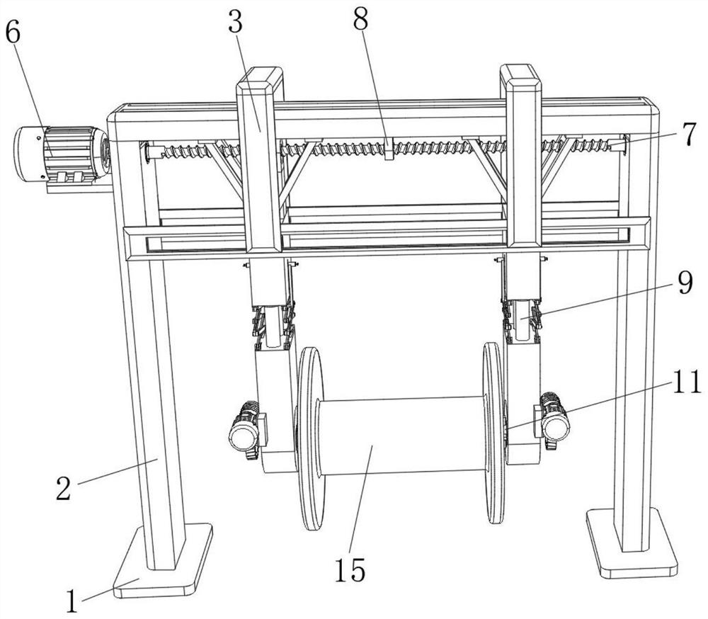
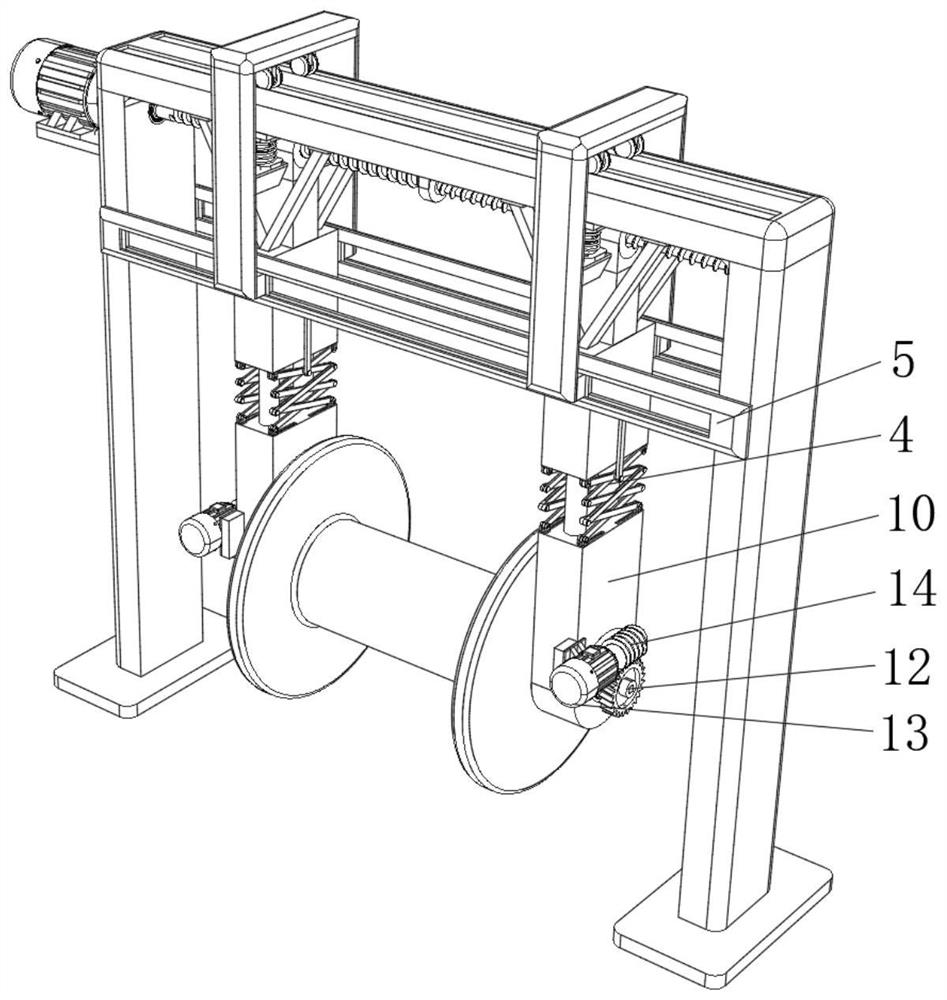
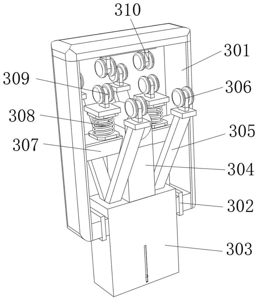
[0025] see Figure 1-4 , the present invention provides a technical solution: an automatic optical cable stranding machine, comprising a fixed base plate 1, the upper surface of the fixed base plate 1 is fixedly connected with a gantry frame 2, and the top of the gantry frame 2 is provided with a force dispersion device 3, which is The bottom of the force dispersion device 3 is provided with an adjustment limiting device 4, the top of the front and back of the...


PUM


Abstract

The invention relates to the technical field of stranding equipment in the cable industry, and discloses an automatic optical cable stranding machine, which includes a fixed bottom plate, the upper surface of the fixed bottom plate is fixedly connected with a gantry frame, and the top of the gantry frame is provided with a force-bearing Dispersion device, the bottom of the force distribution device is provided with an adjustment limit device. The automatic cable twisting machine slides in the sliding groove on the top of the gantry through the first sliding wheel, the second sliding wheel and the third sliding wheel, and cooperates with the weight that the gantry sliding hanger, auxiliary support rod and buffer spring column will bear Disperse, further improve the load-bearing capacity of the gantry, better evenly distribute the force point, avoid the breakage caused by the heavy weight and affect the normal winding work of the optical cable, and also greatly improve the use process. The safety is more convenient for production operation and the convenience of use is improved.

Description

technical field [0001] The invention relates to the technical field of stranding equipment in the cable industry, in particular to an automatic optical cable stranding machine. Background technique [0002] At present, in my country's electrical machinery industry, stranding machine center pay-off frame, lead frame, stranding cage, non-metallic wrapping, cable collection wire mold, meter counter, wheel traction, gantry type take-up and discharge line, ground shaft transmission system, The safety fence is combined, and the cables of the side pay-off rack, the center pay-off rack and the cradle of the twisted cage body are paralleled at the twisted wire mold, and the cables are formed under the rotation of the twisted cage, and after being pulled by wheels The gantry-type winding and winding place is wound into a coil; the current gantry-type winding and twisting machine is generally supported by the guide rail and the guide plate during use; the existing optical cable twisting ...

Claims


Application Information

Patent Timeline
Patent Type & Authority Patents(China)
IPC IPC(8): B65H54/44B65H54/553B65H67/04B65H54/70G02B6/44
CPCB65H54/44B65H54/553B65H54/70B65H67/0417B65H2701/32G02B6/4479G02B6/449
Inventor 尹宣尹树清尹万仓伍建元罗红英
Owner 衡阳市华南电线有限公司
Features
  • R&D
  • Intellectual Property
  • Life Sciences
  • Materials
  • Tech Scout
  • Unparalleled Data Quality
  • Higher Quality Content
  • 60% Fewer Hallucinations
Learn More