Diaphragm water pump

A diaphragm and water pump technology, applied in the field of diaphragm water pumps, can solve the problems of troublesome diaphragm replacement, increase work cost, increase work cost and labor intensity, etc. Effect

Active Publication Date: 2020-11-06
SHENZHEN TCS ELECTRICAL MACHINERY
View PDF7 Cites 0 Cited by
  • Summary
  • Abstract
  • Description
  • Claims
  • Application Information

AI Technical Summary

Problems solved by technology

[0003] The diaphragm in the diaphragm water pump in the prior art is made of specific materials, and each diaphragm is only suitable for one type of liquid. When pumping other types of liquid, it is necessary to replace the pump with a diaphragm of different materials, which will increase the working cost. The scope of use of the water pump is limited. When a matching water pump cannot be found, it is necessary to purchase a new water pump or replace the diaphragm, which increases the problem of work cost and labor intensity
[0004] There are also some schemes about diaphragm water pumps in the prior art, such as patent No. 201710645862.3, the patent name is a patent for a diaphragm pump. The diaphragm water pump made by various mechanisms in this technical scheme has a certain degree of water tightness, which can eliminate or reduce the The effect of vibration, but the sealing of the diaphragm cannot be guaranteed, and at the same time, it is more troublesome to replace the diaphragm

Method used


Image

  • Diaphragm water pump
  • Diaphragm water pump
  • Diaphragm water pump

Examples


Embodiment approach

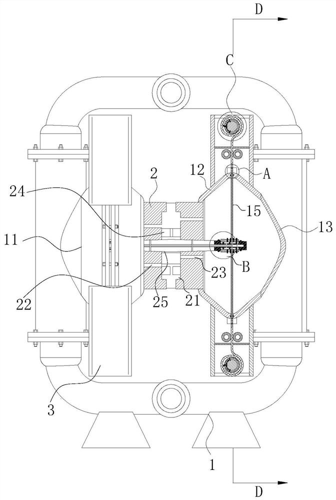
[0034] As an embodiment of the present invention, a circular groove 27 is opened in the inner wall of the driving rod 25, and the circular groove 27 is not connected with the outside; the inner wall of the circular groove 27 is provided with evenly arranged strip-shaped grooves 28, and the strip Shaped groove 28 is all communicated with air groove 21; Said driving rod 25 opposite side is provided with the chute of uniform arrangement in driving rod 25 inwalls, and chute is communicated with round groove 27 by through hole; Each described chute Sliding shafts 29 are connected to the inner walls of the grooves through spring interaction, and the end faces on the opposite side of the sliding shafts 29 are arc-shaped; each said gap 16 is provided with evenly arranged arc-shaped grooves 291 in the inner wall, and the arc-shaped grooves 291 Cooperate with the sliding shaft 29; both sides of the drive rod 25 are provided with evenly arranged trapezoidal grooves 292 in the inner walls ...


PUM


Abstract

The invention belongs to the technical field of diaphragm water pumps, in particular to a diaphragm water pump. The diaphragm water pump comprises a pump body and a moving mechanism. Compression boxesare fixedly connected to the left and right end surfaces of the moving mechanism, and the compression boxes are designed in cone shapes; air slots are formed in the inner wall of the moving mechanismand communicate to high pressure gas; a first gas spray holes which are uniformly arranged are formed in the inner wall of the moving mechanism on the left side of the air holes, and the first gas spray holes communicate to the compression box on the left side; second gas spray holes which are uniformly arranged are formed in the right side of the air holes, and the second gas spray holes communicate to the compression box on the right side. The diaphragm water pump is primarily used for solving the problem that the service range of the water pump is limited as the working cost is improved because it is further need to replace water pump with diaphragms of different materials when extracting other types of liquids as the diaphragm in the diaphragm water pump in the prior art is made froma special material and each diaphragm is only suitable for one liquid.

Description

technical field [0001] The invention belongs to the technical field of diaphragm water pumps, in particular to a diaphragm water pump. Background technique [0002] The diaphragm pump is actually an embolism pump, which uses a membrane to separate the infused liquid from the live column and the pump cylinder, thereby protecting the live column and the pump cylinder. The parts on the left side of the diaphragm that are in contact with the liquid are made of corrosion-resistant materials or coated with a layer of corrosion-resistant substances. The right side of the diaphragm is filled with water or oil. The flow characteristics of the diaphragm pump refer to the relative flow and displacement of the medium flowing through the valve (the relative flow of the valve) The relationship between the ideal flow characteristics mainly includes straight line, equal percentage (logarithmic), parabolic and quick opening. The commonly used ideal flow characteristics are linear, equal per...

Claims


Application Information

Patent Timeline
Patent Type & Authority Applications(China)
IPC IPC(8): F04B43/06F04B43/00
CPCF04B43/06F04B43/0009F04B43/0081
Inventor 张灵辉
Owner SHENZHEN TCS ELECTRICAL MACHINERY
Why Eureka
Try Eureka