A monitoring front end and monitoring device for transmission lines
A technology for power transmission lines and monitoring devices, which is applied in the directions of measuring devices, measuring device casings, measuring instrument components, etc., can solve the problem of high monitoring costs of power transmission lines, and achieve the effects of convenient installation, improved sensitivity, and reduced costs.
- Summary
- Abstract
- Description
- Claims
- Application Information
AI Technical Summary
Problems solved by technology
Method used
Image
Examples
Embodiment 1
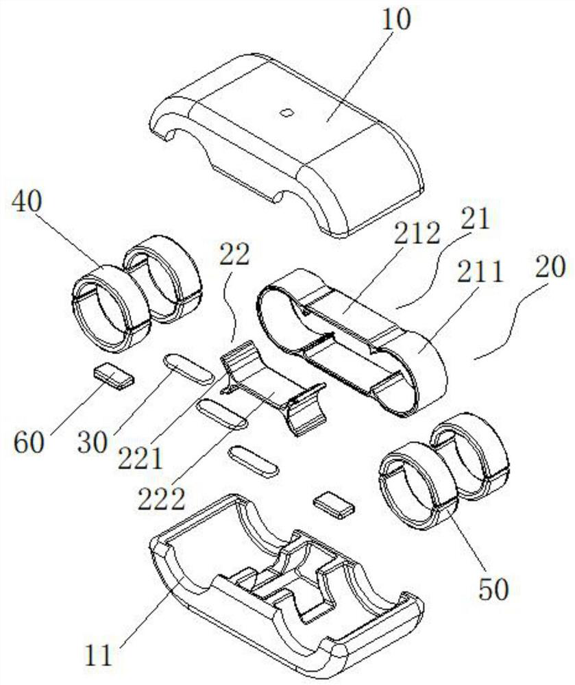
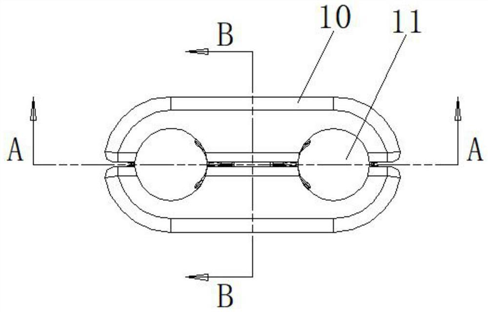
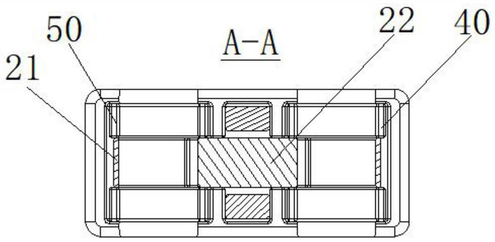
[0031] Such as Figure 1 to Figure 4 As shown, the monitoring front end of the transmission line in the present invention includes a housing 10, an elastic body 20, and a strain gauge 30. The housing 10 is provided with a through hole 11 for the line fitting to pass through. The housing 10 is a detachable Symmetrical structure, the housing 10 is provided with a signal output interface; the elastic body 20 is arranged in the housing 10, and the elastic body 20 is in contact with the line fitting; the strain gauge 30 is arranged on the elastic body 20, and the strain gauge 30 is electrically connected to the signal output interface. connect.
[0032] Such as Figure 4 As shown, the line fittings in this embodiment are U-shaped hanging rings, and there are two through holes 11 on the corresponding housing 10. The housing 10 is a detachable symmetrical structure, and the two are connected by bolts. For fastening connection, the housing 10 is provided with an interface hole 12 at...
Embodiment 2
[0046] The difference between this embodiment and Embodiment 1 is that the structure of the inner elastic body 22 is different, specifically as follows:
[0047] Such as Figure 6 The shown inner elastic body 22 includes a circular arc segment B221 and a connecting segment B222. The number of the circular arc segment B221 is two. The section B222 is in a ring structure, the upper end of the connecting section B222 is arched upwards, the lower end of the connecting section B222 is arched downwards, the strain gauge 30 is set at the arched position of the connecting section B222, and the connecting section B222 is located between the two arc sections B221 In between, the two arc segments B221 are connected by a connecting segment B222.
[0048] Such as Figure 6 As shown, the strain gauges 30 on the outer elastic body 21 are symmetrically arranged on the upper and lower ends of the outer elastic body 21 . The strain gauges 30 on the inner elastic body 22 are symmetrically arr...
Embodiment 3
[0057] The difference between this embodiment and the first embodiment is that the elastic body 20 is a whole.
[0058] Such as Figure 7 As shown, the elastic body 20 is an integral structure, and the two ends are provided with arc structures to abut against the circuit fittings. This structure is simple and easy to install.
PUM
 Abstract
Description
Claims
Application Information
 - R&D
- Intellectual Property
- Life Sciences
- Materials
- Tech Scout
- Unparalleled Data Quality
- Higher Quality Content
- 60% Fewer Hallucinations
Browse by: Latest US Patents, China's latest patents, Technical Efficacy Thesaurus, Application Domain, Technology Topic, Popular Technical Reports.
© 2025 PatSnap. All rights reserved.Legal|Privacy policy|Modern Slavery Act Transparency Statement|Sitemap|About US| Contact US: help@patsnap.com


