Electromagnetic unlocking structure with unlocked state holding function

An unlocked state, electromagnetic technology, applied in the direction of circuits, electrical components, parts of connecting devices, etc., can solve the problems of reduced reliability of separation, complex force distribution, large volume, etc., to improve the safety and reliability of use Effect

Active Publication Date: 2021-12-28
SHANGHAI AEROSPACE SCI & IND ELECTRIC APPLIANCE RES INST
View PDF0 Cites 0 Cited by
  • Summary
  • Abstract
  • Description
  • Claims
  • Application Information

AI Technical Summary

Problems solved by technology

[0003] With the continuous development of multi-stage rockets, the function of the electromagnetic separation connector as the electrical connection between the cabins tends to be integrated, and various types of power contacts, radio frequency contacts, optical fiber The contacts are all mixed in the same electromagnetic separation connector. The number of cores of a single electromagnetic separation connector is increasing, the volume is getting larger and larger, and the force distribution is becoming more and more complicated, which leads to the electromagnetic separation of the electromagnetic separation connector. Reduced reliability of detachment after unlocking
[0004] At present, the electromagnetic unlocking structure commonly used in electromagnetic separation connectors is due to various unexpected reasons after the electromagnetic unlocking. The plug and the socket are not disengaged and separated in time within the time period of the pulse current signal given by the control system. The locking between the plug and the socket The mechanism re-locks automatically. Because of the strong holding force of the locking mechanism, it is difficult to continue to separate from the socket only by pulling the cable at the end of the plug, which will cause the plug and socket to be unable to be disengaged and separated, resulting in mission failure.

Method used


Image

  • Electromagnetic unlocking structure with unlocked state holding function
  • Electromagnetic unlocking structure with unlocked state holding function
  • Electromagnetic unlocking structure with unlocked state holding function

Examples


Embodiment Construction

[0024] In order to make the objectives, technical solutions and advantages of the present invention clearer, the present invention will be further described in detail below with reference to the embodiments. It should be understood that the specific embodiments described herein are only used to explain the present invention, but not to limit the present invention.

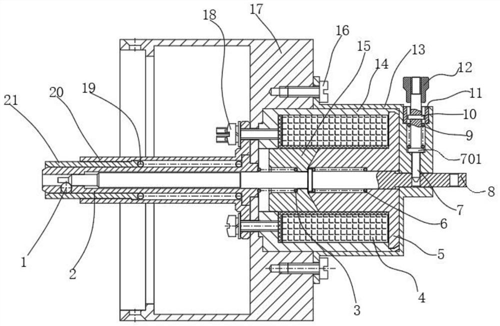
[0025] The electromagnetic unlocking structure with the function of maintaining the unlocked state includes an electromagnetic action joint, a cover 13, a telescopic holding joint, a mechanical locking joint and a tail cover 17; the electromagnetic action joint is installed on the top of the tail cover 17. The mechanical locking joint is installed on the bottom surface of the tail cover 17, the mechanical locking joint is used to assemble the connecting plug joint, and the electromagnetic action joint is used to generate electromagnetic suction to unlock the mechanical locking joint. A cover 13 is installed on the ...


PUM


Abstract

The electromagnetic unlocking structure with the function of maintaining the unlocked state includes that the electromagnetic action assembly is installed on the top surface of the tail cover, the mechanical locking assembly is installed on the bottom surface of the tail cover, and the mechanical locking assembly It is used to assemble the connecting plug assembly, and the electromagnetic action assembly is used to generate electromagnetic suction to unlock the mechanical locking assembly; the outside of the electromagnetic action assembly is equipped with a cover, and the cover is fixed on the tail cover On the top surface, a telescopic holding assembly is embedded inside the cover, and the telescopic holding assembly is mated with the electromagnetic action assembly, and the telescopic holding assembly is used to constrain the positioning of the electromagnetic action assembly; The invention can constrain and position the electromagnetic action combination when it is locked and unlocked, so that the electromagnetic action combination can keep its position and realize the automatic holding function, thereby ensuring structural stability and improving product use safety sex and reliability.

Description

technical field [0001] The invention belongs to the technical field of electromagnetic separation connectors, and particularly relates to an electromagnetic unlocking structure with the function of maintaining unlocked state. Background technique [0002] The electromagnetic separation connector is generally used for the electrical connection and disconnection between the two sections of a two-stage or multi-stage rocket. The socket is fixedly installed on the section 1, and the plug is connected to the section 2 through a cable. The electromagnetic separation connector is docked and locked when the rocket is assembled on the ground, and then launched with the rocket. When the rocket flies in the air to the predetermined time, before the cabin section 1 and the cabin section 2 need to be separated, a pulse electric signal is applied to the electromagnetic unlocking mechanism in the plug through the control system to realize the automatic unlocking between the plug and the so...

Claims


Application Information

Patent Timeline
Patent Type & Authority Patents(China)
IPC IPC(8): H01R13/629H01R13/502H01R13/62
CPCH01R13/629H01R13/6205H01R13/502
Inventor 卢贵斌李虎
Owner SHANGHAI AEROSPACE SCI & IND ELECTRIC APPLIANCE RES INST
Why Eureka
Try Eureka