Supercharge Your Innovation With Domain-Expert AI Agents!

A real-time optical cable situation monitoring system

A monitoring system and optical cable technology, applied in the field of real-time optical cable situation monitoring system, can solve the problems of inability to quickly determine the actual location of the fault, long time to find the fault, and difficulty in locating the fault point, etc., and achieve simple structure, fast transmission speed, and improved work efficiency effect

Active Publication Date: 2022-07-12
JIANGSU ELECTRIC POWER CO +1
View PDF9 Cites 0 Cited by
  • Summary
  • Abstract
  • Description
  • Claims
  • Application Information

AI Technical Summary

Problems solved by technology

This method of cable troubleshooting requires a large number of well-trained professionals in the field to clear the fault. Generally, it takes a long time to find the fault, and it is difficult to locate the fault point. It is impossible to quickly determine the actual location of the fault, resulting in low work efficiency.

Method used


Image

  • A real-time optical cable situation monitoring system
  • A real-time optical cable situation monitoring system
  • A real-time optical cable situation monitoring system

Examples


Embodiment 1

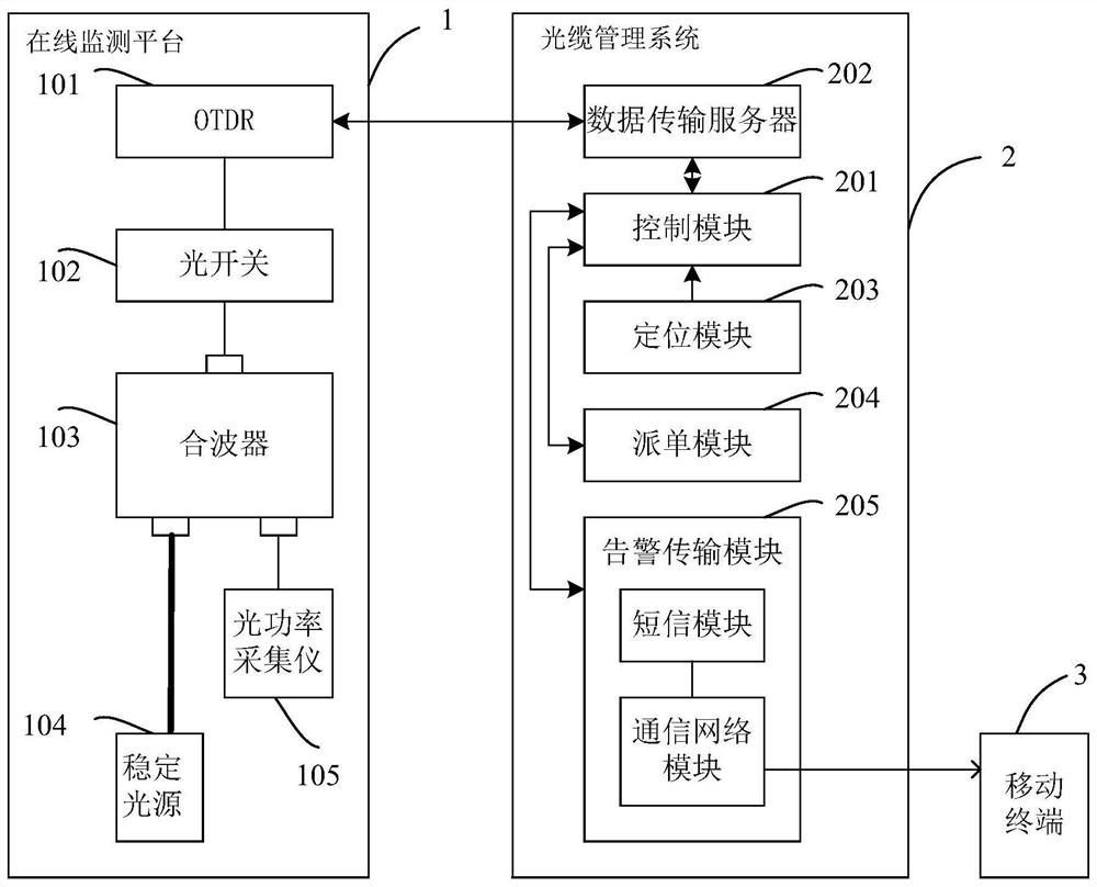
[0031] Please refer to figure 1 and figure 2 , The present invention is a real-time optical cable situation monitoring system, which includes an online monitoring platform 1 , an optical cable management system 2 , and a mobile terminal 3 .

[0032] The online monitoring platform 1 includes an optical time domain reflectometer 101, an optical switch 102, a combiner 103, an optical power collector 105 and a stable light source 104; wherein the optical time domain reflectometer 101 is electrically connected to the optical switch 102, and the optical switch 102 is connected to For the single port of the multiplexer 103, the optical cable under test is located between the stable light source 104 and one of the working ports of the multiplexer 103, and the other working port of the multiplexer 103 is connected to the optical power collector 105;

[0033] The optical time domain reflectometer 101 is the OTDR, which is responsible for sending the test optical signal to the optical ...

Embodiment 2

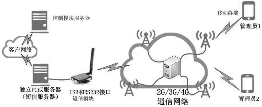
[0048] see image 3 , the difference between this embodiment and the first embodiment lies in the composition of the alarm transmission module 205 , and the rest of the structures are the same, which will not be repeated here. In this embodiment, the alarm transmission module 205 includes a short message module electrically connected to the control module 201 through a serial port and a communication network module for realizing signal transmission between the short message module and the mobile terminal 3; the short message module adopts an industrial-grade 4G LTE MODEM , the short message module is equipped with an independent host computer, the host computer is a short message server, and the 4GLTE MODEM is connected to the short message server through the RS232 interface to transfer the USB cable. Interaction, use the same network to push the alarm information generated by the control module 201 in the optical cable monitoring system to the short message server, and then s...


PUM


Abstract

The invention relates to the technical field of optical cable monitoring, in particular to a real-time optical cable situation monitoring system, which is characterized in that: it includes an online monitoring platform, an optical cable management system and a mobile terminal; the online monitoring platform includes an optical time domain reflectometer, an optical switch, The optical cable management system includes a control module, a data transmission server, a positioning module, an order dispatch module, and an alarm transmission module that are electrically connected to the control module; the data transmission server is connected to the optical time domain reflectometer for signal connection, alarming The transmission module is used for signal transmission between the optical cable management system and the wireless terminal; the alarm transmission module includes a short message module electrically connected to the control module through a serial port and a communication network module for realizing signal transmission between the short message module and the mobile terminal; To receive the optical cable fault repair task list. The invention detects the optical cable signal in real time, and improves the work efficiency in the process of repairing the fault of the optical cable.

Description

technical field [0001] The invention relates to the technical field of optical cable monitoring, in particular to a real-time optical cable situation monitoring system. Background technique [0002] For a long time, the maintenance of optical cables has been carried out by maintenance personnel using simple instruments and their own accumulated experience for many years. In many cases, due to external damage and the influence of the natural environment, the maintenance of optical cables is difficult, cumbersome and inefficient. Maintenance personnel are under a lot of work pressure and high workload. [0003] The traditional optical cable operation and maintenance is mainly to measure the approximate position of the optical cable manually by OTDR (optical time domain reflectometer) after the optical cable fails. This method of troubleshooting optical cables requires a large number of well-trained professionals in the field to clear the fault. Generally, it takes a long time...

Claims


Application Information

Patent Timeline
Patent Type & Authority Patents(China)
IPC IPC(8): H04B10/071H04B10/079
CPCH04B10/071H04B10/0791H04B10/07955
Inventor 孔小红蒋陵杨林青管翰林王乐蒙夏冰皮一晨王文帝
Owner JIANGSU ELECTRIC POWER CO
Features
  • R&D
  • Intellectual Property
  • Life Sciences
  • Materials
  • Tech Scout
  • Unparalleled Data Quality
  • Higher Quality Content
  • 60% Fewer Hallucinations
Learn More