Supercharge Your Innovation With Domain-Expert AI Agents!

Steel pipe rotary flushing device

A steel pipe and water flushing technology, which is applied in the direction of cleaning hollow objects, cleaning methods and utensils, chemical instruments and methods, etc., can solve problems such as misjudgment and alarm of flaw detection work, failure to wash the steel pipe wall, troublesome cleaning by customers, etc., to achieve flushing High quality, stable operation, rinse clean without residue effect

Pending Publication Date: 2020-11-10
TIANJIN UNITED STEEL PIPE
View PDF6 Cites 0 Cited by
  • Summary
  • Abstract
  • Description
  • Claims
  • Application Information

AI Technical Summary

Problems solved by technology

[0002] During the production process of steel pipes, when the steel pipes come off the production line, some impurities such as scale, iron scraps, and scratches will remain on the inner wall. In the production of modern enterprises, the requirements for steel pipes are getting higher and higher. These retained impurities will give subsequent The fault detection work will cause misjudgment and alarm, which will also bring troubles to the subsequent further anti-corrosion coating process, and will also bring troubles to customers for later cleaning
In order to remove these impurities, the method of water flushing is usually used, but in the past water flushing, the steel pipe is mostly in a static state, so when the water flows in the steel pipe, it will gradually sink, that is, there will be gaps at the top of the last section of the steel pipe , causing part of the wall surface of the steel pipe to not be washed, seriously affecting the quality of washing, and bringing hidden dangers to the use of steel pipes

Method used


Image

  • Steel pipe rotary flushing device
  • Steel pipe rotary flushing device
  • Steel pipe rotary flushing device

Examples


Embodiment Construction

[0025] The present invention will be further described in detail below through the specific examples, the following examples are only descriptive, not restrictive, and cannot limit the protection scope of the present invention with this.

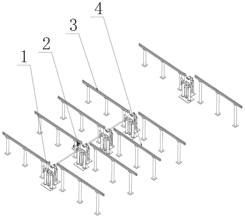
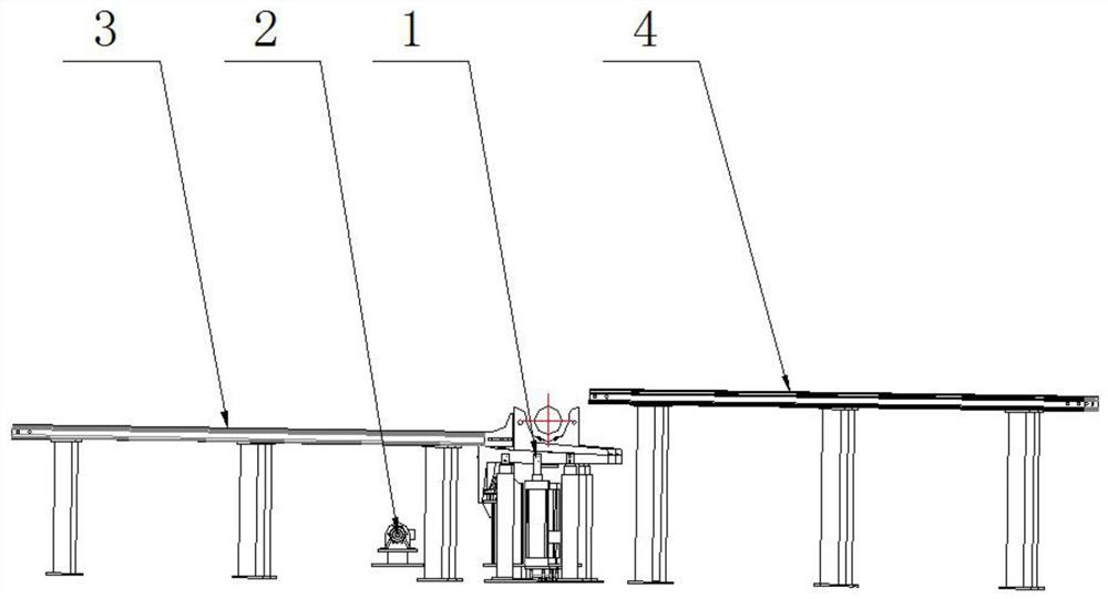
[0026] A steel pipe rotary flushing device, which consists of a feeding platform 3, a feeding platform 4, a pipe transfer mechanism 1, and a rotating mechanism 2. The frame and the unloading platform are located on both sides.

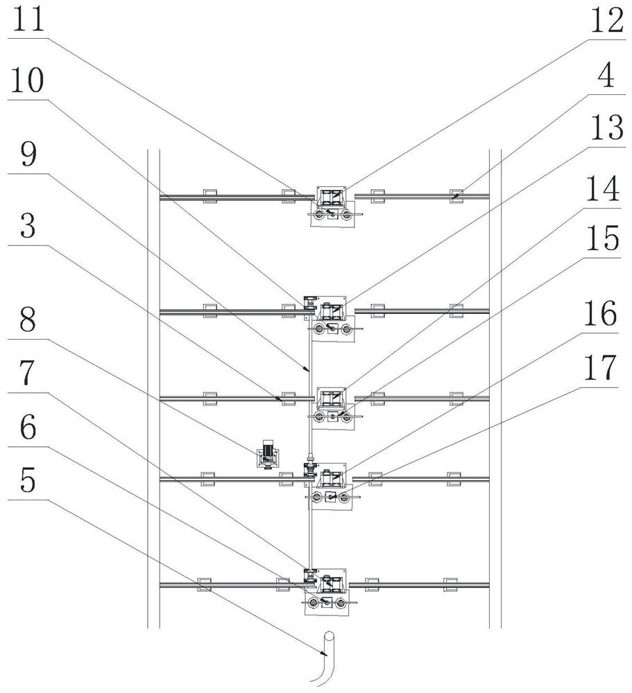
[0027] Pipe transfer mechanism, including the first cylinder turner 6, the second cylinder turner 17, the third cylinder turner 15, the fourth cylinder turner 10, the fifth cylinder turner 11, the first cylinder turner 1. The material turning device of the second cylinder, the material turning device of the third cylinder, the material turning device of the fourth cylinder, and the material turning device of the fifth cylinder are coaxially set at intervals corresponding to the length of the steel pipes.

[0028] Th...


PUM


Abstract

The invention belongs to the technical field of steel pipe production equipment, and relates to a steel pipe rotary flushing device. The steel pipe rotary flushing device is characterized by comprising a feeding rack, a discharging rack, a pipe moving mechanism and a rotating mechanism; the pipe moving mechanism and the rotating mechanism are arranged in the middle in a front-back close mode according to different sizing lengths of steel pipes, and the feeding rack and the discharging rack are arranged on the two sides correspondingly; the pipe moving mechanism comprises a first air cylinder upender, a second air cylinder upender, a third air cylinder upender, a fourth air cylinder upender and a fifth air cylinder upender; and the first air cylinder upender, the second air cylinder upender, the third air cylinder upender, the fourth air cylinder upender and the fifth air cylinder upender are coaxially arranged at intervals corresponding to the length of the steel pipe. The steel pipe rotary flushing device is scientific and reasonable in structural design, has the advantages of being clean in flushing, free of residues, high in flushing quality, capable of conducting feeding and discharging at the same time, high in speed, high in efficiency, stable in operation, wide in application range and the like, and has high innovativeness.

Description

technical field [0001] The invention belongs to the technical field of steel pipe production equipment, and in particular relates to a steel pipe rotary flushing device. Background technique [0002] During the production process of steel pipes, when the steel pipes come off the production line, some impurities such as scale, iron scraps, and scratches will remain on the inner wall. In the production of modern enterprises, the requirements for steel pipes are getting higher and higher. These retained impurities will give subsequent The fault detection work will cause misjudgment and alarm, which will also bring troubles to the subsequent further anti-corrosion coating process, and will also bring troubles to customers for later cleaning. In order to remove these impurities, the method of water flushing is usually used, but in the past water flushing, the steel pipe is mostly in a static state, so when the water flows in the steel pipe, it will gradually sink, that is, there ...

Claims


Application Information

Patent Timeline
Patent Type & Authority Applications(China)
IPC IPC(8): B08B9/032B08B13/00
CPCB08B9/0321B08B13/00B08B2209/032
Inventor 徐龙庆梁德友
Owner TIANJIN UNITED STEEL PIPE
Features
  • R&D
  • Intellectual Property
  • Life Sciences
  • Materials
  • Tech Scout
  • Unparalleled Data Quality
  • Higher Quality Content
  • 60% Fewer Hallucinations
Learn More