Transmission, vehicle power system and vehicle
A power system and transmission technology, applied in the field of vehicle transmission and vehicle power system, can solve problems such as energy loss, poor performance, and the engine cannot be directly driven, and achieve the effect of ensuring performance
- Summary
- Abstract
- Description
- Claims
- Application Information
AI Technical Summary
Problems solved by technology
Method used
Image

Examples
Embodiment Construction
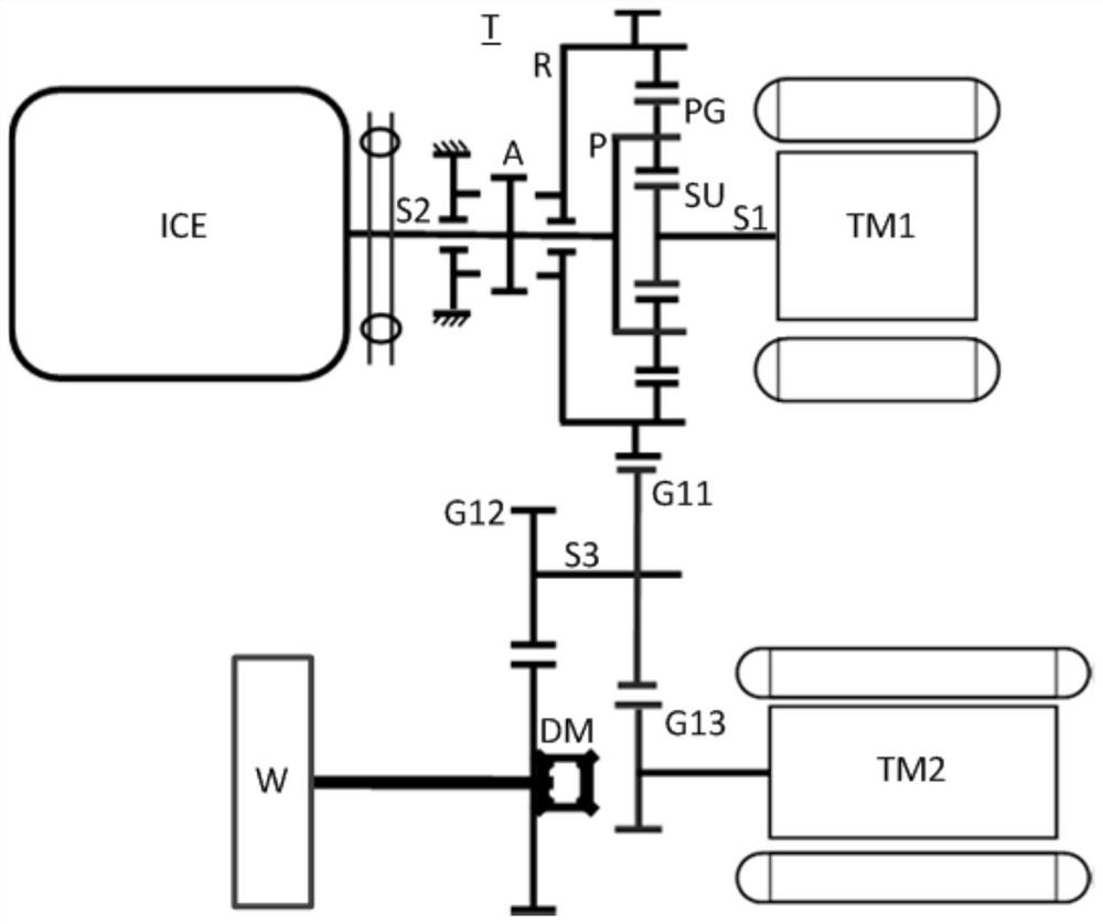
[0046] Exemplary embodiments of the present invention are described below with reference to the accompanying drawings. It should be understood that these specific descriptions are only used to teach those skilled in the art how to implement the present invention, but are not intended to exhaust all possible ways of the present invention, nor are they intended to limit the scope of the present invention. In the present invention, "transmission coupling" refers to the ability to transmit torque between two components, and unless otherwise specified, means that the two components are directly connected or transmit torque through a gear mechanism or the like. The structure of a power system for a vehicle according to a first embodiment of the present invention will first be described below.
[0047] (Structure of Power System for Vehicle According to First Embodiment of the Present Invention)
[0048] Such as figure 1 As shown, the vehicle power system according to the first emb...
PUM
 Abstract
Description
Claims
Application Information
 - R&D
- Intellectual Property
- Life Sciences
- Materials
- Tech Scout
- Unparalleled Data Quality
- Higher Quality Content
- 60% Fewer Hallucinations
Browse by: Latest US Patents, China's latest patents, Technical Efficacy Thesaurus, Application Domain, Technology Topic, Popular Technical Reports.
© 2025 PatSnap. All rights reserved.Legal|Privacy policy|Modern Slavery Act Transparency Statement|Sitemap|About US| Contact US: help@patsnap.com