Support bonding equipment and bonding method

A bonding method and bonding technology, applied in mechanical equipment, lighting and heating equipment, connecting components, etc., can solve the problems of low production efficiency, inability to bond different types of brackets, high cost, etc., and achieve high production efficiency and improve Bonding accuracy and work efficiency, cost reduction effect

Active Publication Date: 2020-11-10
FUJIAN WANDA AUTOMOBILE GLASS IND
View PDF10 Cites 1 Cited by
  • Summary
  • Abstract
  • Description
  • Claims
  • Application Information

AI Technical Summary

Problems solved by technology

[0008] The technical problem to be solved by the present invention is to provide a bracket bonding equipment, which aims to solve the technical problems of high cost, low production efficiency and inability to apply to different types of bracket bonding in the bracket bonding equipment in the prior art

Method used


Image

  • Support bonding equipment and bonding method
  • Support bonding equipment and bonding method
  • Support bonding equipment and bonding method

Examples


Embodiment 1

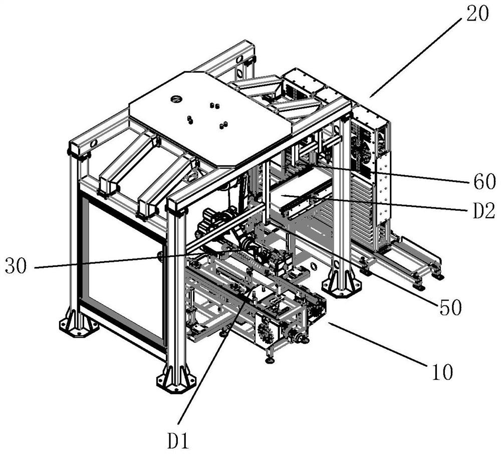
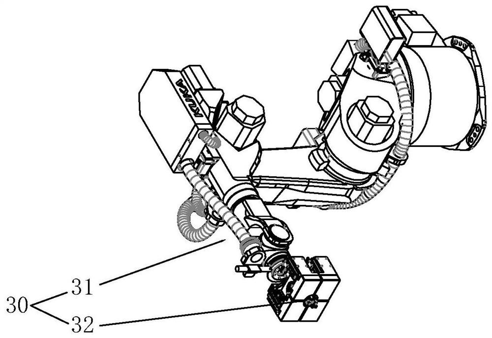
[0034] Please refer to figure 1 , figure 2 , Figure 4 as well as Figure 6, the present embodiment provides a bracket bonding equipment, which is characterized in that it includes: a glass plate conveying device 10, a support 100 conveying device 20, a clamping device 30, and a control device; the glass plate conveying device 10 is used to transport the glass plate to the first position D1; the stent 100 delivery device 20 is used to transport the stent 100 to the second position D2; the clamping device 30 can move to the second position D2 to clamp the stent 100, and stick the stent 100 to the A preset area on the surface of the glass plate at the first position D1; a twistable post 101 is arranged on the side opposite to the bonding surface of the support 100, and the clamping device 30 includes: a manipulator 31. Clamping mechanism 32 and clamping mouth; Clamping mechanism 32 is connected to the working end of described manipulator 31, and has at least one pair of mout...

Embodiment 2

[0054] Please refer to Figures 1 to 6, this embodiment provides a bracket bonding method applied to the above-mentioned bracket bonding equipment. For the structure of the bracket bonding equipment, refer to the content of the embodiment. The bracket bonding method includes the following steps:

[0055] S10. The glass conveying device conveys the glass plate to the first position D1;

[0056] S20. The stent 100 transport device 20 transports the stent 100 to the second position D2;

[0057] S30. The adjustment mechanism 13 lifts up the glass plate located in the first position D1, and adjusts the angle of the preset area on the glass plate relative to the horizontal plane;

[0058] S40. The centering mechanism 12 centers the glass plate lifted by the adjustment mechanism 13;

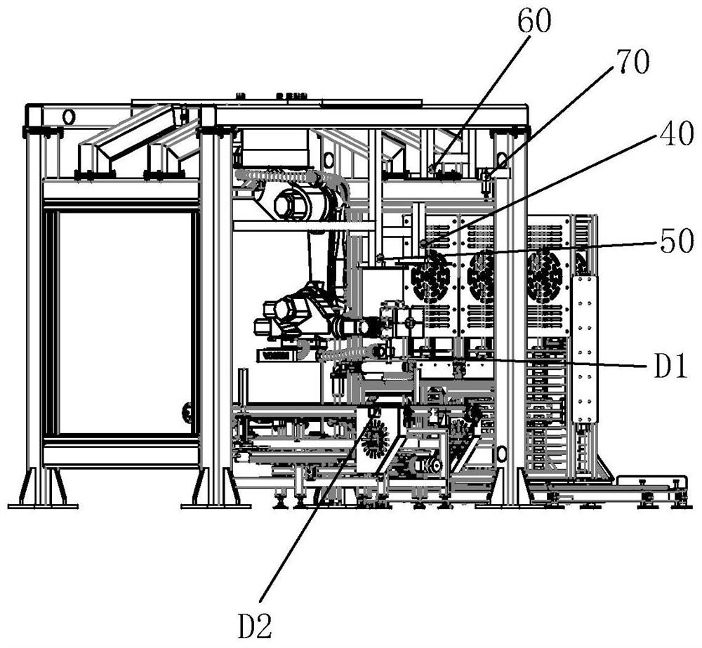
[0059] S50. The first visual device 40 obtains the first information including the type information of the support 100 and the position information of the column 101 of the support 100, and the second...


PUM


Abstract

The invention discloses support bonding equipment. The support bonding equipment comprises a glass plate conveying device, a support conveying device, a clamping device, and a control device, whereinthe glass plate conveying device is used for conveying a glass plate to a first position, the support conveying device is used for conveying a support to a second position, the clamping device can bemoved to the second position to clamp the support and paste the support to a preset area on the surface of the glass plate located at the first position, a column body is arranged on the surface, opposite to the bonding surface of the support, of the support, the clamping device comprises a manipulator, and a clamping mechanism, the clamping mechanism is connected to the working end of the manipulator and is provided with at least one pair of mouth parts which can be close to each other, and grooves corresponding to the peripheral shape of the column body are formed in the opposite surfaces ofthe two mouth parts. The support bonding equipment has the advantages that the cost is reduced, the production efficiency is high, and the support bonding equipment is suitable for alternate production occasions for pasting different types of supports.

Description

technical field [0001] The invention relates to the technical field of vehicle glass production, in particular to bracket bonding equipment. [0002] The present invention also relates to a stent bonding method applied to the above-mentioned stent bonding device. Background technique [0003] Electronic components such as car cameras and rain sensors are usually installed on the inner surface of the car windshield through brackets. With the development of society, the number of electronic components on the windshield increases, which in turn makes brackets for buckling electronic components types also increased. [0004] In the prior art, for different types of brackets, people usually stick the brackets manually at preset positions on the windshield. However, manual bonding of the brackets has inaccurate bonding and positioning, which cannot achieve streamlined operation, and the efficiency is low. , The disadvantage of poor bonding effect. [0005] Later, people thought...

Claims


Application Information

Patent Timeline
Patent Type & Authority Applications(China)
IPC IPC(8): B65G47/90B65G43/08B65G49/06B65G15/12F16B11/00
CPCB65G15/12B65G43/08B65G47/90B65G49/061B65G49/063B65G49/067B65G2203/0208F16B11/006
Inventor 史智勇林福团张金舜李兴旺杨志雄叶宗凯黄健兴张奇林姚学宇付代华金东东
Owner FUJIAN WANDA AUTOMOBILE GLASS IND
Why Eureka
Try Eureka