A municipal drainage ditch and its construction method

A drainage ditch and municipal technology, applied in waterway systems, water supply devices, sewer pipe systems, etc., can solve problems such as limited drainage capacity of gutters, impact on pedestrians and vehicles, and impact on the urban environment, so as to increase flood discharge capacity and reduce random drifting effect

Active Publication Date: 2021-11-02
HEILONGJIANG COLLEGE OF CONSTR
View PDF4 Cites 0 Cited by
  • Summary
  • Abstract
  • Description
  • Claims
  • Application Information

AI Technical Summary

Problems solved by technology

The current drainage ditch can only realize the drainage function, but the drainage capacity of the current drainage ditch is limited. When the rainfall is large, there will still be too much water on the road, which will affect the travel of pedestrians and vehicles; The domestic garbage in the city is easy to float over the drains at will, affecting the urban environment, and it is more troublesome for cleaners to clean up

Method used


Image

  • A municipal drainage ditch and its construction method
  • A municipal drainage ditch and its construction method
  • A municipal drainage ditch and its construction method

Examples


specific Embodiment approach 1

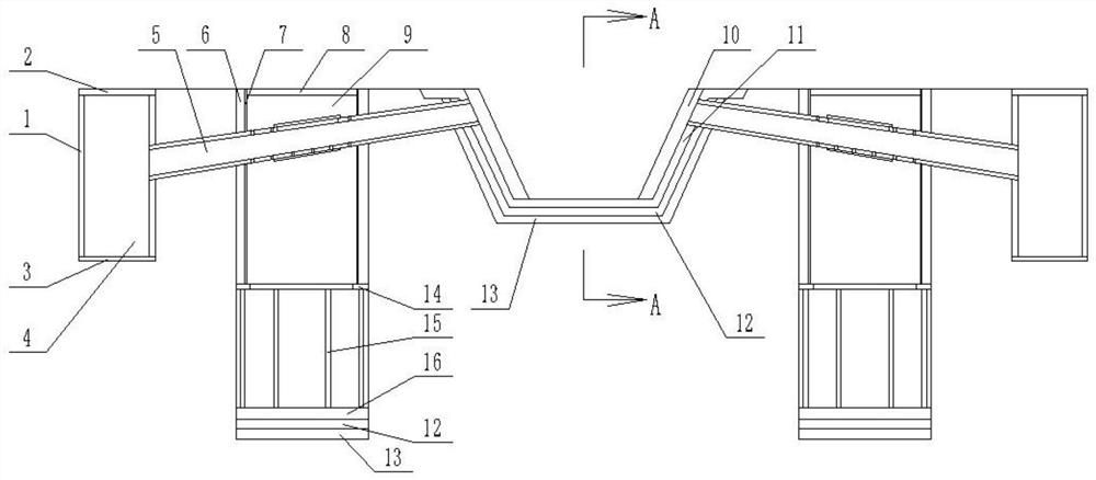
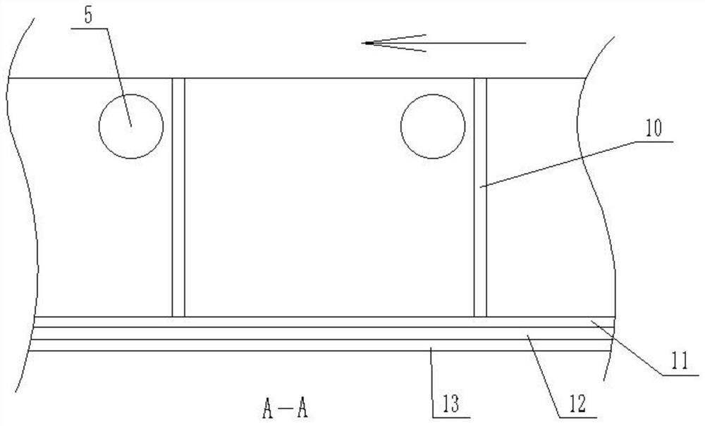
[0019] Specific implementation mode one: as Figure 1-Figure 4 As shown, this embodiment describes a municipal drainage ditch, including a ditch body; the municipal drainage ditch also includes a pipe 5, a masonry layer 6, a cement layer 7, a manhole cover II 8, a shaft II 9, and a cement cushion 11 , gravel layer 12, fine sand layer 13, annular backing plate 14, pillar 15, bottom plate II 16; the interior of the trench body is laid with fine sand layer 13, gravel layer 12, cement cushion 11 from bottom to top; The vertical shaft II9 is ​​arranged on the side of the trench body, and the distance between the vertical shaft II9 and the trench body is 2-3m; the bottom plate II16 is fixedly arranged at the bottom of the vertical shaft II9, and the lower end of the bottom plate II16 is provided with a gravel layer 12 and a fine sand layer 13; The lower end of the pillar 15 is fixedly connected to the bottom plate II 16, and the upper end of the pillar 15 is fixedly connected to the...

specific Embodiment approach 2

[0020] Specific implementation mode two: as Figure 1-Figure 4 As shown, this embodiment is a further description of the first embodiment, and the depth of the shaft II9 is ​​greater than twice the depth of the groove body. The rainwater can infiltrate into the deep soil faster, and the flood discharge capacity of the present invention is increased.

specific Embodiment approach 3

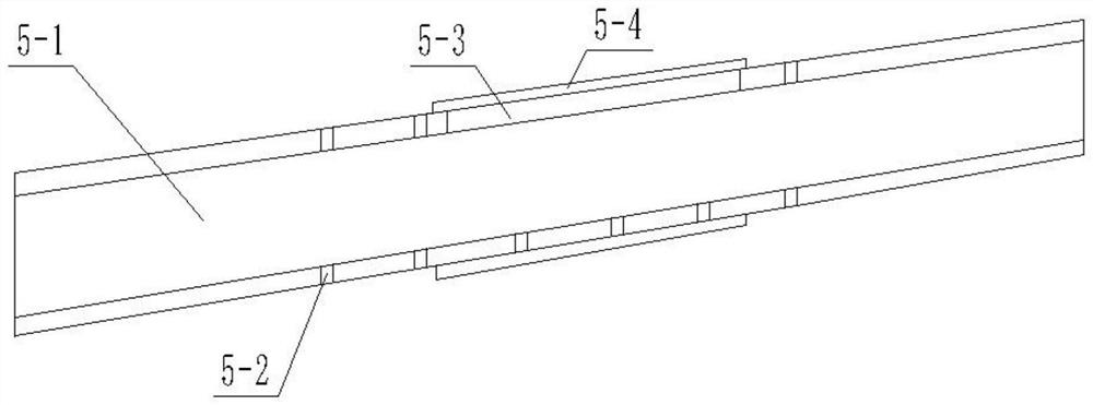
[0021] Specific implementation mode three: as Figure 1-Figure 4 As shown, this embodiment is a further description of specific embodiment 1. The pipe 5 includes a pipe main body 5-1; the middle position of the pipe main body 5-1 is provided with a plurality of penetrating pipe main body 5-1 wall thicknesses. The through hole 5-2; the through hole 5-2 is located in the shaft II9. It is used to drain the rainwater in the pipe 5 into the shaft II9.


PUM


Abstract

A municipal drainage ditch and a construction method thereof belong to the field of municipal drainage. The interior of the trench body is laid with a fine sand layer, a crushed stone layer, and a cement cushion from bottom to top; the bottom plate II is fixed at the bottom of the shaft II, and the lower end of the bottom plate II is provided with a gravel layer and a fine sand layer; The masonry layer is fixedly connected to the annular backing plate, and the masonry layer is attached to the inner wall of the shaft II; the cement layer is arranged on the inner wall of the masonry layer; the manhole cover II is movably connected to the upper end of the masonry layer; The pipe is laid on the ground, and one end of the pipe communicates with the trench body, the pipe passes through the shaft II, and the middle part of the pipe communicates with the shaft II. The present invention is provided with shaft II, and the lower end of the annular backing plate of shaft II is directly connected with the soil, and after rainwater enters shaft II, it can directly infiltrate into the deep soil, increasing the flood discharge capacity of the drainage ditch; , the household garbage can be directly flowed into the shaft I through the pipe, so as to reduce the random drifting of the household garbage with the rainwater.

Description

technical field [0001] The invention relates to a municipal drainage ditch and a construction method thereof, belonging to the field of municipal drainage. Background technique [0002] In order to prevent too much water accumulation in the city from affecting pedestrians and vehicles, cities set up drainage ditches. The current drainage ditch can only realize the drainage function, but the drainage capacity of the current drainage ditch is limited. When the rainfall is large, there will still be too much water on the road, which will affect the travel of pedestrians and vehicles; The domestic garbage in the area is easy to float over the drains at will, affecting the urban environment, and it is more troublesome for cleaners to clean up. Contents of the invention [0003] The object of the present invention is to provide a municipal drainage ditch and its construction method to solve the above-mentioned problems in the background technology. [0004] The present inventi...

Claims


Application Information

Patent Timeline
Patent Type & Authority Patents(China)
IPC IPC(8): E03F3/04E03F3/06
CPCE03F3/046E03F3/06
Inventor 郭启臣边喜龙王晶田东军李钊袁忠文蒋俊山李宝昌
Owner HEILONGJIANG COLLEGE OF CONSTR
Why Eureka
Try Eureka