Flood discharge structure of concrete gravity dam

A technology of flood discharge structure and gravity dam, applied in gravity dams, dams, water conservancy projects, etc., can solve the problems of large amount of downstream energy dissipation and anti-scour measures, cumbersome gate opening and closing scheduling procedures, and increased metal structure engineering, etc. The effect of increasing the width of the water inlet front, saving the consumption and improving the flood discharge capacity

Pending Publication Date: 2021-02-02
SHANGHAI INVESTIGATION DESIGN & RES INST
View PDF0 Cites 0 Cited by
  • Summary
  • Abstract
  • Description
  • Claims
  • Application Information

AI Technical Summary

Problems solved by technology

[0004] 1. Surface hole discharge method: Generally, in order to ensure the drainage capacity, when the surface hole does not have a gate, the width of the water inlet front is large, resulting in a large downstream drainage width and a great impact on the downstream slope; when the surface hole is equipped with a gate , resulting in an increase in the amount of metal structure engineering, resulting in cumbersome gate opening an

Method used


Image

  • Flood discharge structure of concrete gravity dam
  • Flood discharge structure of concrete gravity dam
  • Flood discharge structure of concrete gravity dam

Examples


Example Embodiment

[0039]The following specific examples illustrate the implementation of the present invention. Those familiar with the technology can easily understand other advantages and effects of the present invention from the content disclosed in this specification.

[0040]It should be noted that the structure, ratio, size, etc. drawn in the drawings of this specification are only used to match the content disclosed in the specification for the understanding and reading of those familiar with the technology, and are not used to limit the implementation of the present invention. Therefore, it has no technical significance. Any structural modification, proportional relationship change, or size adjustment should still fall within the scope of the present invention without affecting the effects and objectives that can be achieved by the present invention. The technical content can cover the range. At the same time, the terms "center", "vertical", "horizontal", "upper", "lower", "front", "rear", "left...


PUM


Abstract

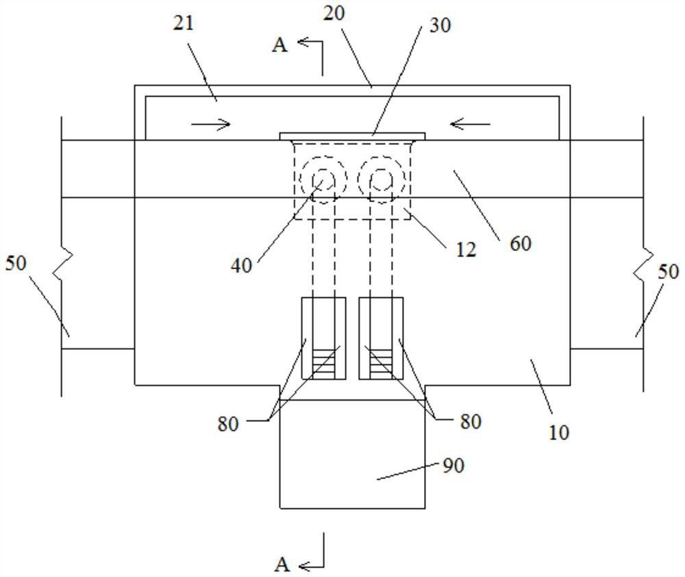
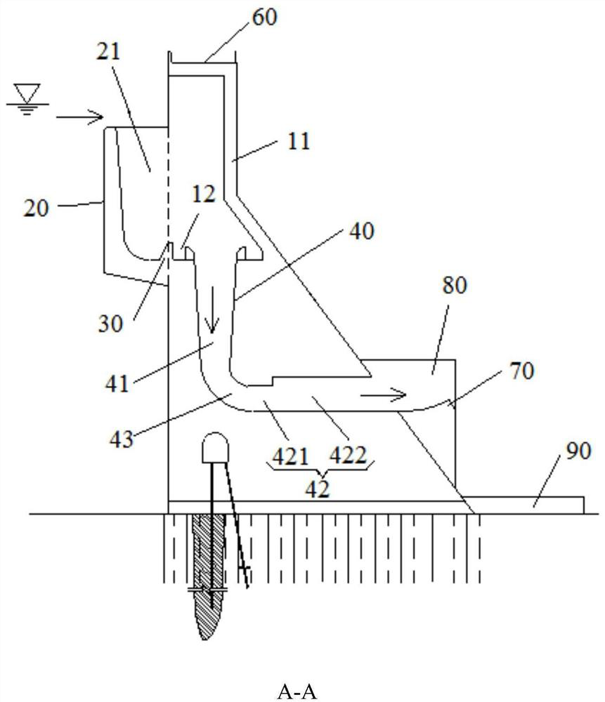
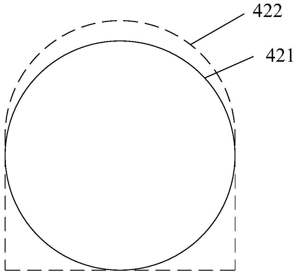
The invention provides a flood discharge structure of a concrete gravity dam. The structure is arranged at an overflow dam section of the concrete gravity dam. The flood discharge structure comprisesa water retaining wall of the overflow dam section, an overflow wall distributed at the upstream side of the water retaining wall, an overflow groove formed in the downstream side of the overflow wall, a water collecting pool formed at the upstream side of the water retaining wall, a stilling sill arranged at the bottom of the water collecting pool, and a vertical shaft type spillway formed in theoverflow dam section. The vertical shaft type spillway comprises a vertical shaft flood discharge section, a horizontal flood discharge section and a connecting flood discharge section connected between the vertical shaft flood discharge section and the horizontal flood discharge section; the upper end of the vertical shaft flood discharge section extends to the bottom of the water collecting pool and is communicated with the water collecting pool; and an outlet of the horizontal flood discharge section is located in a downstream river channel. According to the flood discharge structure of the concrete gravity dam, by arranging the overflow wall, the width of a water inlet front edge can be increased, and the flood discharge capacity is improved; and discharged water flow is collected through the water collecting pool, so that the width of the discharged water flowing into a river is reduced, energy dissipation is conducted on the discharged water flow through the stilling still and the vertical shaft type spillway, and scouring of the discharged water flow to a downstream side slope is reduced.

Description

technical field [0001] The invention relates to the technical field of water conservancy and hydropower engineering design, in particular to a flood discharge structure of a concrete gravity dam. Background technique [0002] As a water conservancy and hydropower project for retaining flood water and regulating water flow, the reservoir plays an important role in flood control, irrigation, power generation and water supply. Water-retaining and water-releasing structures are an important part of the reservoir's ability to perform these functions. [0003] In water conservancy and hydropower projects, in addition to topographic and geological conditions, dam type is the main factor determining the layout of drainage structures. Concrete gravity dams can take advantage of their own characteristics to use the dam body for flood discharge; in general, the dam body of concrete gravity dams has surface holes, middle holes, or a combination of surface holes and middle holes. Among...

Claims


Application Information

Patent Timeline
IPC IPC(8): E02B8/06E02B7/10E02B8/00
CPCE02B7/10E02B8/00E02B8/06
Inventor 巩绪威邹浩黄盛铨
Owner SHANGHAI INVESTIGATION DESIGN & RES INST
Why Eureka
Try Eureka