Diaphragm pump with pressure regulating and one-way reverse osmosis functions

A technology of reverse osmosis and diaphragm pump, applied in the direction of pump with flexible working elements, pump, pump control, etc., can solve the damage of diaphragm pump, does not have the functions of pressurization, pressure regulation and one-way reverse osmosis, cannot solve the problem of diaphragm pump Outlet pressure problems and other problems, to achieve the effect of stable working pressure, compact structure and small volume

Pending Publication Date: 2020-11-10
NINGBO AMBER MOTOR MFG
View PDF0 Cites 0 Cited by
  • Summary
  • Abstract
  • Description
  • Claims
  • Application Information

AI Technical Summary

Problems solved by technology

However, the existing diaphragm pumps do not have the functions of pressurization, pressure regulation and one-way reverse osmosis, and cannot solve the problem of diaphragm pump outlet pressure in practical applications. When the pressure difference between the inlet and outlet is too large, it will affect the normal operation of the diaphragm pump, which is very serious. It is easy to cause damage to the diaphragm pump

Method used


Image

  • Diaphragm pump with pressure regulating and one-way reverse osmosis functions
  • Diaphragm pump with pressure regulating and one-way reverse osmosis functions
  • Diaphragm pump with pressure regulating and one-way reverse osmosis functions

Examples


Embodiment Construction

[0020] Embodiments of the present invention will be described in further detail below in conjunction with the accompanying drawings.

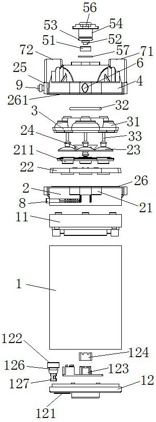
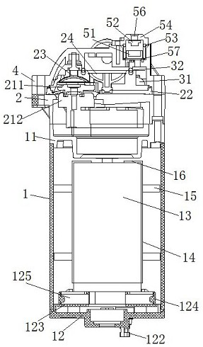
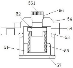
[0021] Figures 1 to 3 It is a structural representation of the present invention.

[0022] The reference signs therein are: pump body 1, first end cover 11, second end cover 12, outlet hole 121, outlet protective cover 122, carbon brush support frame 123, carbon brush buckle 124, carbon brush 125, anti-clip Groove 126, waterproof sealing tube 127, drive motor 13, limit structure 14, connecting rod 15, annular limit plate 16, support frame 2, eccentric balance wheel 21, piston piece 211, piston rod 212, diaphragm body 22, suction Check valve 23, discharge check valve 24, second support frame 25, annular card groove 26, annular bead 261, mounting bracket 3, diaphragm chamber 31, O-ring 32, hollow connecting rod 33, fluid chamber 4, regulator Pressure device 5, spring base 51, spring cover plate 52, top cover sealing ring 53, small top cover 54...


PUM


Abstract

The invention discloses a diaphragm pump with pressure regulating and one-way reverse osmosis functions. The diaphragm pump comprises a pump body, a first end cover and a supporting frame, wherein aneccentric balance wheel is arranged in the supporting frame, an output shaft of a driving motor penetrates through the first end cover and extends into the supporting frame to be fixedly connected with the eccentric balance wheel, a diaphragm body and a piston piece used for driving the diaphragm body to move are integrated at the top of the eccentric balance wheel, a suction check valve and a discharge check valve are integrated at the top of the piston piece, a diaphragm chamber is arranged above the suction check valve and the discharge check valve through a mounting support, the bottom ofthe diaphragm chamber is connected with the suction check valve through a hollow connecting rod, an O-ring is arranged at the top of the mounting support, a fluid chamber is arranged at the top of thesupporting frame through a second supporting frame, a pressure regulating device is arranged in the fluid chamber, a second end cover is arranged at the bottom of the pump body, and two carbon brushes are transversely installed at the top of the second end cover through carbon brush buckles. The diaphragm pump is compact in structure, small in size, convenient to disassemble and assemble and capable of controlling the fluid flow to adjust the internal pressure in the working process of the diaphragm pump.

Description

technical field [0001] The invention relates to the technical field of diaphragm pumps, in particular to a diaphragm pump with functions of pressure regulation and one-way reverse osmosis. Background technique [0002] Diaphragm pump is a special form of positive displacement pump. It relies on the back and forth agitation of a diaphragm to change the volume of the working chamber to suck people and discharge liquid. With the development and progress of science and technology, diaphragm pumps have made breakthroughs in materials. At present, diaphragm pumps are widely used in chemical, environmental protection, metallurgy, pharmaceutical and other industries. The transmission medium is separated from the transmission mechanical parts, which effectively prevents the medium from leaking out, and the pump body itself has no shaft liquid seal, so the service life is greatly extended, and it has an irreplaceable position with other pumps. However, the existing diaphragm pumps d...

Claims


Application Information

Patent Timeline
Patent Type & Authority Applications(China)
IPC IPC(8): F04B43/04F04B49/08F04B49/22
CPCF04B43/0081F04B43/04F04B49/08F04B49/22F04B49/225
Inventor 李勉
Owner NINGBO AMBER MOTOR MFG
Why Eureka
Try Eureka