
Flexible lighting device control system

A lighting device and control system technology, applied in the direction of lighting devices, lamp circuit layout, light source, etc., can solve the problem of impact current damage to the chopper, etc., and achieve the effect of flexible operation, excellent performance, and simple structure

Inactive Publication Date: 2014-01-29
SHAANXI QIYUAN TECH DEV
View PDF0 Cites 1 Cited by
  • Summary
  • Abstract
  • Description
  • Claims
  • Application Information

AI Technical Summary

Problems solved by technology

Although the series compensated PWM AC regulator has the advantages of high efficiency and no harmonic pollution, the inrush current will still damage the chopper

Method used


Image

  • Flexible lighting device control system
  • Flexible lighting device control system
  • Flexible lighting device control system

Examples


Embodiment Construction

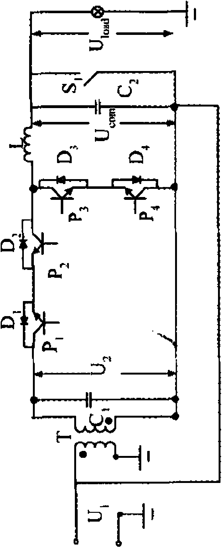
[0008] As shown in the figure, the flexible lighting device control system of the present invention is composed of a bidirectional AC BUCK chopper, an LC filter and a compensation transformer connected in series.

[0009] exist figure 1 middle, The secondary side voltage of the parallel transformer is also the input voltage of the AC chopper, is the output voltage of the chopper,

[0010] and transformer primary side voltage The phase difference is 180 degrees. Assuming that the transformation ratio of the transformer is n, and D is the duty cycle, the voltage on the secondary side of the transformer can be obtained for:

[0011]

[0012] The relationship between the output of the AC chopper and the input voltage is:

[0013]

[0014] Depend on figure 1 It can be seen that

[0015]

[0016] Combine (1), (2), (3) to get

[0017]

[0018] Formula (4) expresses: According to , changing the duty cycle D, t...


PUM


Abstract

The invention relates to a lighting control circuit, in particular to a flexible lighting device control system. The flexible lighting device control system is formed by connecting a two-way alternate-current BUCK chopper, an LC filter and a compensated transformer in series. The flexible lighting device control system is simple in structure, flexible in operation and excellent in performance, and has the function of adjusting and stabilizing voltages.

Description

technical field [0001] The invention relates to a lighting control circuit. Background technique [0002] With the rapid advancement of science and technology, the traditional rigid lighting system, as an unchanging lighting method, does not meet the modern energy-saving requirements. The lighting system that came into being is called a flexible lighting control system. This system is based on the characteristic that there is a nonlinear relationship between the illuminance and the absorbed power, thereby satisfying the need for a flexible lighting system with controllable brightness. The flexible lighting control device should have the following characteristics: 1. As a power-saving control device, it has high working efficiency; 2. It can be suitable for many different types of lighting loads; 3. It can ensure the stability and reliability of the device operation. Especially in important occasions such as shopping malls, banks, subways, airports, etc., power failure cann...

Claims


Application Information

Patent Timeline
Patent Type & Authority Applications(China)
IPC IPC(8): H05B37/02
Inventor 王梅玫
Owner SHAANXI QIYUAN TECH DEV
Learn More