
Electrical connectors and their terminals

An electrical connector and terminal technology, applied in the field of automotive electrical connectors and their terminals, can solve the problems of uneven force, corroded board surface, inability to fully fit, etc., and achieve the effect of continuous and stable contact

Active Publication Date: 2021-11-16
DEYI PRECISION ELECTRONIC IND CO LTD PANYU
View PDF4 Cites 0 Cited by
  • Summary
  • Abstract
  • Description
  • Claims
  • Application Information

AI Technical Summary

Problems solved by technology

[0002] An existing automobile terminal includes a sheet-shaped first contact portion and a second contact portion stacked with the first contact portion. Since the sheet material used to manufacture the automobile terminal itself has a certain thickness and hardness, it must be folded in the second contact portion. During the processing of the first contact part and the second contact part, a certain gap inevitably appears in the bending part between the first contact part and the second contact part, so that the first contact part and the second contact part The second contact portion cannot be completely attached at the bend, but at the side edge on the opposite side to the bend, the first contact portion and the second contact portion are bonded together Yes, when the automobile terminal is inserted and fixed to an insulating body, the first contact portion and the second contact portion are pressed from the inner wall of the insulating body and deform toward the gap, and when the When the first contact portion and the second contact portion are inserted into the butt terminal, in order to maintain a stable electrical connection between the automobile terminal and the butt terminal, the butt terminal will clamp and squeeze the first contact part or the plate surface of the second contact part, so that the first contact part or the second contact part at the clamping place deforms toward the gap. It can be seen from the above that when the automobile terminal is fixed on the When the insulating body is to be docked with the butt terminal, the first contact portion and the second contact portion of the automobile terminal will bear different pressures from the insulating body and the butt terminal at different positions. Therefore, the stress on the first contact portion and the second contact portion will be uneven, and the contact area between the first contact portion and the second contact portion and the butt terminal will be different. , thereby affecting the continuous and stable electrical connection between the first contact portion and the second contact portion and the butt terminal
[0003] In addition, when the automobile terminal is immersed in electroplating solution for electroplating treatment, the electroplating solution will enter between the first contact part and the second contact part through the gap, because the first contact part and the second contact part The side edges on the other side of the two contact parts are bonded together, and the uneven force on the first contact part and the second contact part can easily lead to failure to ensure that the first contact part and the second contact part The gap exists between the two contact parts, so the electroplating solution cannot flow out of the gap in time and remains in the gap. Over time, the electroplating solution will corrode the board surfaces of the first contact part and the second contact part , reducing the service life of the automotive terminal

Method used


Image

  • Electrical connectors and their terminals
  • Electrical connectors and their terminals
  • Electrical connectors and their terminals

Examples


Embodiment Construction

[0034] In order to facilitate a better understanding of the purpose, structure, features and effects of the present invention, the present invention will now be further described with reference to the accompanying drawings and specific embodiments.

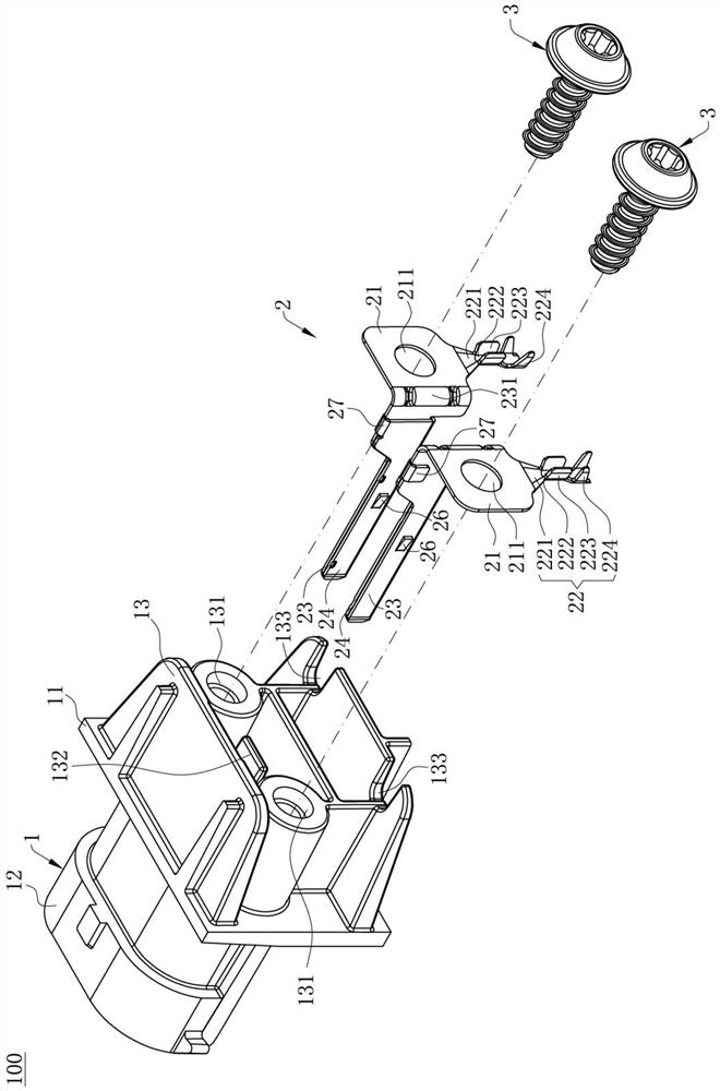
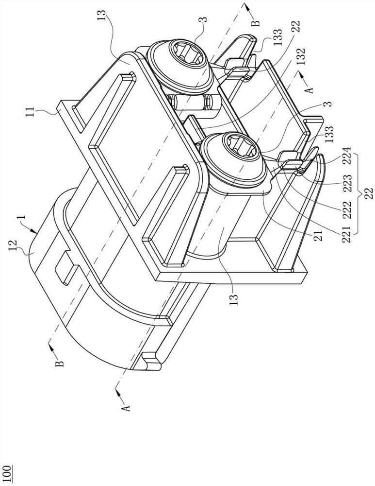
[0035] see figure 1 , this is the electrical connector 100 of the present invention, which is used for docking with a mating connector (not shown). The electrical connector 100 is used for automobile fog lamps. The electrical connector 100 includes an insulating body 1 along the The two terminals 2 of the insulating body 1 are inserted in the front-rear direction, and the two screws 3 that fix the terminals 2 to the insulating body 1 . The mating connector is provided with a mating piece (not shown) that is mated with the terminal 2 .

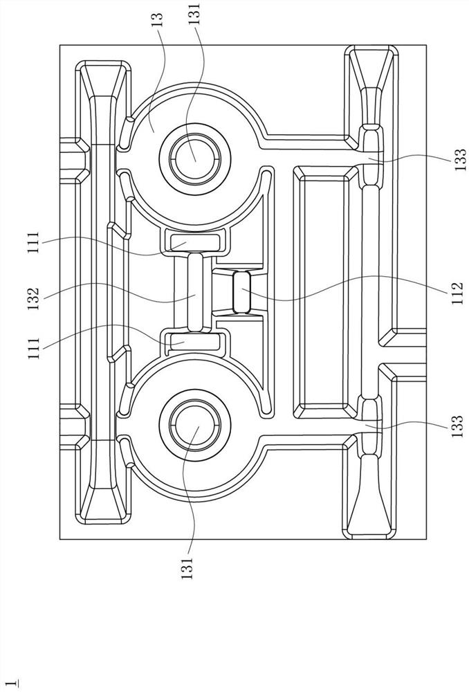
[0036] see figure 1 and Figure 5 , the insulating body 1 includes a fixing portion 11 , a docking portion 12 extending forward from the fixing portion 11 , and a mounting portion 13 extending b...


PUM


Abstract

The invention discloses an electrical connector and its terminal, which are used to connect with a mating piece along the front and rear direction, comprising: a connecting part, an electrical conducting part, a first plate extending from the connecting part and a connecting part connected with the second connecting part. A second plate connected to the side edge of the first plate, the extension direction of the first plate and the second plate is the same, there is a gap between the first plate and the second plate, a first contact piece is provided on the front section of the first plate, the second plate The front section of the second plate is provided with a second contact piece opposite to the surface of the first contact piece. The first contact piece and the second contact piece are used to be inserted into the mating piece and formed by stamping from the surface of the first plate or the second plate. A holding part is located behind the first contact piece and the second contact piece, a first protruding part protrudes from the first plate or the second plate to the gap and is located in front of the holding part, and a second protruding part is formed from the first The plate or the second plate protrudes to the gap and is located behind the holding part to ensure the gap between the first plate and the second plate, so that the first contact piece, the second contact piece and the docking piece can be in continuous and stable contact.

Description

【Technical field】 [0001] The present invention relates to an electrical connector and its terminal, in particular to an automobile electrical connector and its terminal. 【Background technique】 [0002] An existing automobile terminal includes a sheet-shaped first contact portion and a second contact portion stacked with the first contact portion. Since the sheet material for manufacturing the automobile terminal itself has a certain thickness and hardness, it is difficult to fold the first contact portion. During the processing of a contact portion and a second contact portion, a certain gap will inevitably appear in the bent portion between the first contact portion and the second contact portion, so that the first contact portion and the second contact portion inevitably have a certain gap. The second contact portion cannot be completely fitted at the bend, but on the side edge on the other side opposite to the bend, the first contact portion and the second contact portion...

Claims


Application Information

Patent Timeline
Patent Type & Authority Patents(China)
IPC IPC(8): H01R13/04
CPCH01R13/04
Inventor 顾正文杨国辉
Owner DEYI PRECISION ELECTRONIC IND CO LTD PANYU
Learn More