Pay-off mechanism for electric power construction

A technology of electric construction and rotating mechanism, which is applied in cable laying equipment, overhead line/cable equipment, and arrangement using take-up reel/photosensitive drum, etc. problems, to achieve the effect of smooth pay-off process, improved pay-off efficiency, and easy sorting.

Active Publication Date: 2020-11-10
国网安徽省电力有限公司怀远县供电公司
View PDF5 Cites 2 Cited by
  • Summary
  • Abstract
  • Description
  • Claims
  • Application Information

AI Technical Summary

Problems solved by technology

[0004] Based on the technical problems that the existing pay-off mechanism for electric power construction is prone to jamming due to the change of the position of the wire end when the cabl

Method used


Image

  • Pay-off mechanism for electric power construction
  • Pay-off mechanism for electric power construction
  • Pay-off mechanism for electric power construction

Examples


Embodiment 1

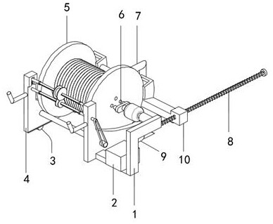
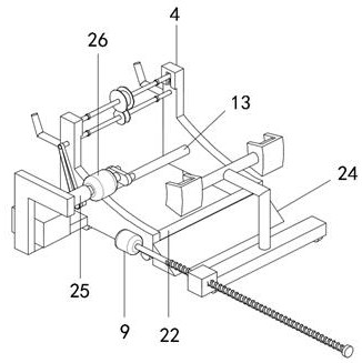
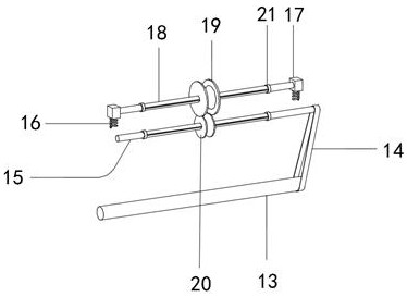
[0029] refer to Figure 1-4 , a pay-off mechanism for electric power construction, comprising a wire reel 5, a universal wheel 3, a slant plate 24, a base 4 and a movable plate 10, the outer wall of one side of the base 4 is connected with a first support rod 13 and a second support through a bearing Rod 22, one end of the first supporting rod 13 penetrates through one side of the outer wall of the base 4 and is sleeved with a track 14, and the top of one side of the outer wall of the base 4 is connected with a first rotating shaft 15 through a bearing, and the first rotating shaft 15 and the first supporting rod 13 pass through The crawler belt 14 is connected, the outer wall of the first rotating shaft 15 is sleeved with a small wire feeding wheel 20, one side outer wall of the base 4 is provided with a chute, the bottom inner wall of the chute is fixed with a spring 16 by screws, and the top of the spring 16 is fixed with a screw. The base block 17, the outer wall of one si...

Embodiment 2

[0037] refer to Figure 5, a pay-off mechanism for electric power construction. Compared with Embodiment 1, this embodiment also includes the outer walls on both sides of the wire reel 5, which are fixed with limiting blocks 27 by screws.

[0038] In the present invention, the inner walls of both sides of the bracket 11 are provided with locking grooves 28 .

[0039] In the present invention, the limiting block 27 is engaged with the locking groove 28 .

[0040] During use, when the cable on the reel 5 is paid out, continue to rotate the reel 5 so that the limit block 27 partly rotates to the inner wall of the slot 28 of the bracket 11, then close the second motor 26, and start the electric push rod 25 to retract Piston rod, start the first motor 9 again to drive the screw mandrel 8 to rotate, and the screw mandrel 8 rotates to drive the movable plate 10 to drive the support 11 to move away from the direction of the swash plate 24. At this time, the support 11 pulls the wire ...


PUM


Abstract

The invention discloses a pay-off mechanism for electric power construction, and provides the following scheme for solving the problems that an existing pay-off mechanism for electric power construction is prone to being jammed due to changes of the position of a cable end when a cable is drawn out, pay-off efficiency is reduced, and the sheath of the cable is abraded when jamming is caused, and the pay-off mechanism comprises a wire coil, universal wheels, an inclined plate, a base and a movable plate. A first supporting rod and a second supporting rod are connected to the outer wall of one side of the base through bearings, one end of the first supporting rod penetrates through the outer wall of one side of the base to be sleeved with a crawler belt, and a first rotating shaft is connected to the top of the outer wall of one side of the base through a bearing. Sliding strips are bonded to the outer walls of the first rotating shaft and the second rotating shaft, and the small wire feeding wheel and the large wire feeding wheel can slide on the outer walls of the first rotating shaft and the second rotating shaft through the sliding strips, so the small wire feeding wheel and thelarge wire feeding wheel can transversely move along with the positions of wire ends when cables are drawn out, the pay-off process is smooth and not prone to blockage, and cable skin abrasion is avoided, and the cable is protected.

Description

technical field [0001] The invention relates to the field of cable pay-off technology, in particular to a pay-off mechanism for electric power construction. Background technique [0002] Electricity is an energy powered by electric energy. It was invented in the 1870s. The invention and application of electric power set off the second industrialization climax and became one of the three scientific and technological revolutions in the world since the 18th century in human history. Since then, technology has changed people. The daily life is a power production and consumption system composed of power generation, power transmission, power transformation, power distribution, and power consumption. It converts primary energy in nature into electricity through mechanical energy devices, and then converts it Power is supplied to various users, and power transmission is one of the most important links. [0003] Power transmission requires a lot of manpower, material resources and f...

Claims


Application Information

Patent Timeline
IPC IPC(8): H02G1/04H02G1/06H02G11/02
CPCH02G1/04H02G1/06H02G11/02
Inventor 金鑫
Owner 国网安徽省电力有限公司怀远县供电公司
Why Eureka
Try Eureka