A non-transmission automatic reversing structure based on machinery

A non-transmission, automatic commutation technology, applied in the field of mechanical transmission, can solve the problems of slow commutation speed and unfavorable rapid commutation, and achieve the effects of high commutation efficiency, simple adjustment and cost saving.

Active Publication Date: 2021-08-10
浙江昂科工程技术有限公司
View PDF12 Cites 0 Cited by
  • Summary
  • Abstract
  • Description
  • Claims
  • Application Information

AI Technical Summary

Problems solved by technology

[0006] The purpose of the present invention is to provide a non-transmission automatic reversing structure based on machinery to solve the problem that the currently used rotating shaft reversing proposed in the above background technology mainly uses a contactor to control the steering of a three-phase motor to convert the direction of rotation. The speed is slow, which is not conducive to fast reversing, and it is impossible to realize the problem of fast reversing of the transmission system during the mechanical operation.

Method used


Image

  • A non-transmission automatic reversing structure based on machinery
  • A non-transmission automatic reversing structure based on machinery
  • A non-transmission automatic reversing structure based on machinery

Examples


Embodiment Construction

[0030] Next, the technical solutions in the embodiments of the present invention will be apparent from the embodiment of the present invention, and it is clearly described, and it is understood that the described embodiments are merely embodiments of the present invention, not all of the embodiments.

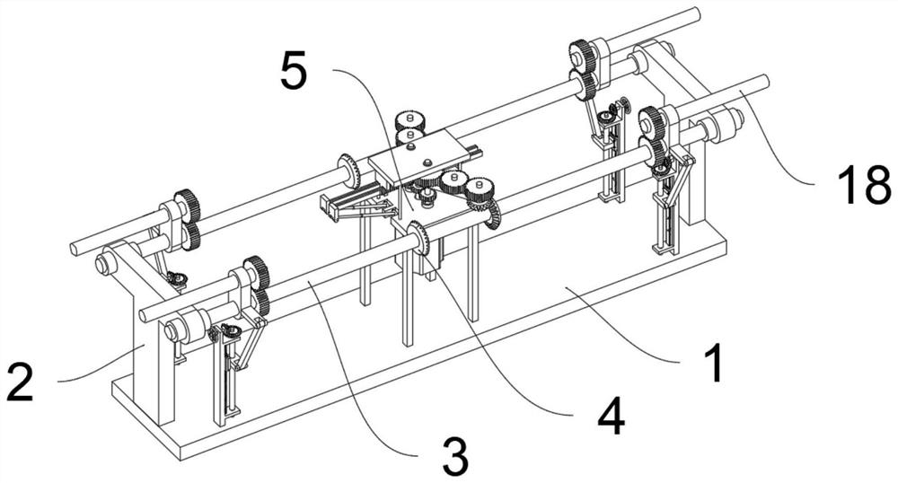
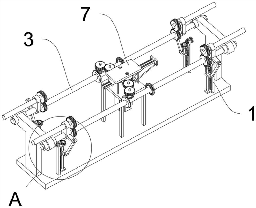
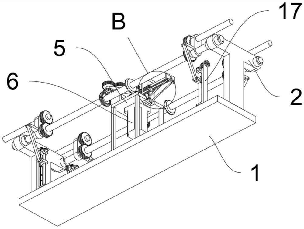
[0031] See Figure 1 to 8One embodiment of the present invention is: one is a mechanical non-conductive automatic automatic commutation structure including a base 1; two side sides of the top of the base 1 are fixedly provided with two sets of driven bobbin 2; from the moving bobbin 2 For the T-shaped structure, the two sets of two sets of driven shafts 2 are rotated between the two sets of driven shafts 3; the outer side of the driven shaft 3 is fixedly disposed with two sets of reversing gear 4, and the reversing gear 4 All are the cone gear, the same side reverse gear 4 tooth surface is opposite; the top of the base 1 is fixed to the frame 5; the intermediate bottom portion of the...


PUM


Abstract

The invention discloses a non-transmission automatic commutation structure based on machinery, relates to the technical field of mechanical transmission, and solves the problem that the commutation of a rotating shaft currently used mainly controls the steering of a three-phase motor through a contactor to convert the rotation direction, and the commutation speed Slow, not conducive to the problem of fast commutation. A non-transmission type automatic reversing structure based on machinery, comprising a base; two sets of driven axle brackets are fixedly arranged on both sides of the top of the base; the driven axle brackets are all T-shaped structures, and two sets of driven axles are provided. Two sets of driven shafts are rotatably arranged between the two sides of the top of the frame; two sets of reversing gears are fixed on the outside of the driven shafts, and the reversing gears are all bevel gears, and the tooth surfaces of the reversing gears on the same side are opposite to each other. , by being provided with a reversing axle frame and a sliding rack, the reversing axle frame is provided with a fast reversing function. The hydraulic cylinder is used to drive the sliding rack to move, and the toothed structure of the reversing axle frame can be engaged by the sliding rack. Adjust the angle of the reversing shaft bracket.

Description

Technical field [0001] The present invention relates to the field of mechanical transmission, in particular, a mechanical non-driving automatic automatic commutation structure. Background technique [0002] The shaft is a cylindrical article in the middle of the bearing or in the middle of the wheel or in the middle of the wheel or the gear, but there are also fewer partial. The shaft is a mechanical parts that support the rotating part and rotate in one of them to transmit movement, torque or bending moment, and is also the main use of the main use. [0003] A patent, for example, a patent number CN207677590U discloses a structure for positioning a commutator and a rotating shaft, including a shaft, a core, a commutator body, and a wire having a winding, the iron core. On the side, a connecting sleeve is provided, and the connecting sleeve is provided with a commutator body, and the shaft passes through the core, a connection sleeve and a commutator body, and the interior of the...

Claims


Application Information

Patent Timeline
Patent Type & Authority Patents(China)
IPC IPC(8): H02P1/40H02K7/116H02K7/06
CPCH02K7/06H02K7/116H02K7/1163H02P1/40
Inventor 张宇洋
Owner 浙江昂科工程技术有限公司
Why Eureka
Try Eureka