a wire take-up device

A wire take-up device and roller technology, applied in the directions of transportation and packaging, thin material handling, and filamentary material transportation, can solve the problems of lengthening the lateral distance between the nozzle and the roller, multi-layered materials, poor rigidity, etc., and improve traction. effect, the effect of reducing the multi-layered material and improving the rigidity

Active Publication Date: 2020-04-28
广东顺德三扬科技股份有限公司
View PDF5 Cites 0 Cited by
  • Summary
  • Abstract
  • Description
  • Claims
  • Application Information

AI Technical Summary

Problems solved by technology

[0002] The wire take-up machine is a kind of equipment that winds a thread-like object onto a specific workpiece, especially for the storage of zipper floss. The existing wire take-up machine generally includes a swing arm, a nozzle and a drum. The nozzle passes through the swing arm. It is located on the upper side of the drum, and its lower end is provided with a feed port. One end of the zipper floss is wound on the drum through the feed port, and the zipper floss is wound on the drum through periodic axial translation and rotation of the drum. The material level of the dental floss wound on the drum is constantly rising, and the material nozzle will gradually rise with the material level under the action of the swing arm. In addition, the zipper floss will shake during the winding process. In order to ensure that the material nozzle does not collide with the material surface, the height distance between the material nozzle and the material surface can only be increased, but at the same time the material nozzle is also lengthened. The lateral distance between the roller and the roller makes the part between the zipper floss from the nozzle to the roller too long, resulting in slow response of the nozzle when the roller changes direction, poor material guide rigidity, and easy multi-layer stacking when changing directions bad phenomenon

Method used


Image

  • a wire take-up device
  • a wire take-up device
  • a wire take-up device

Examples


Embodiment Construction

[0019] A preferred embodiment of the present invention will be described below with reference to the accompanying drawings.

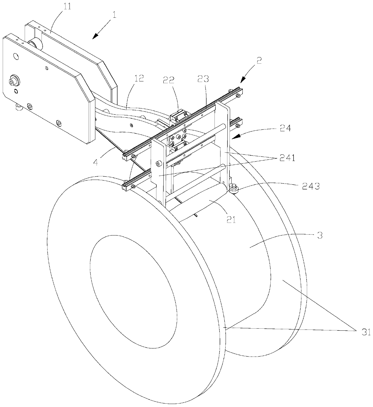
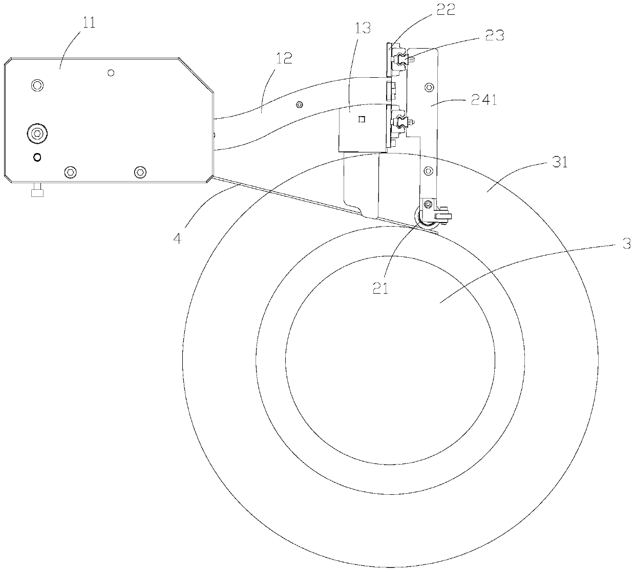
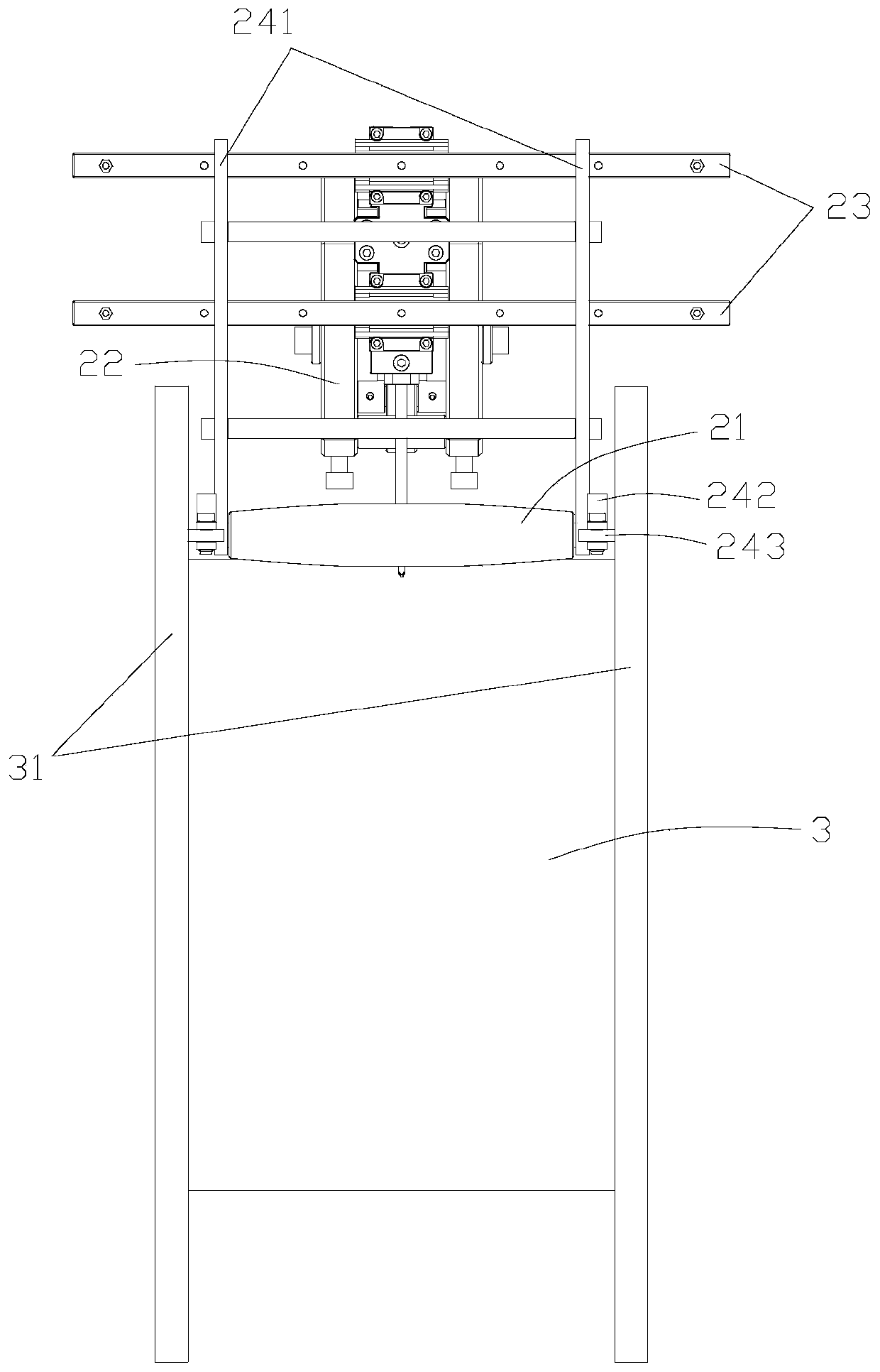
[0020] see Figure 1 to Figure 5 , the present embodiment provides a wire take-up device, including a guiding mechanism 1, a material pressing mechanism 2, a drum 3 and a driving mechanism (the driving mechanism is not shown in the figure), and the driving mechanism includes a motor for driving the rotating motion of the drum 3 A rotation drive mechanism and a translation drive mechanism that drives the drum 3 to move periodically in axial translation. The guide mechanism 1 includes a material guide base 11, a connecting rod 12 and a nozzle 13. The head end of the connecting rod 12 is hinged to the material guide base 11, so that the connecting rod 12 can reciprocate in the up and down direction. , the material nozzle 13 is located at the end of the connecting rod 12, the lower end of the material nozzle 13 is provided with a material hole 131, the mat...


PUM


Abstract

The invention belongs to the technical field of zipper dental floss storage equipment, in particular to a wire take-up device. The wire take-up device comprises a guide mechanism, a pressing mechanism, a roller and a driving mechanism; the driving mechanism drives the roller for rotation and periodical axial translation; the guide mechanism comprises a guide base, a connecting rod and a material mouth; the head end of the connecting rod is hinged to the guide base, so that the connecting rod can swing back and forth in the up-down direction; the material mouth is arranged at the tail end of the connecting rod; the material mouth is arranged on the upper side of the roller; the pressing mechanism is arranged on the outer side of the material mouth, and is connected with the tail end of theconnecting rod through a transverse slide rail mechanism; the pressing mechanism comprises a pressing roller positioned at the lower end and capable of rotating; limiting surfaces are arranged on twoopposite sides of the roller; the lower end width of the pressing mechanism is matched with the transverse distance between the limiting surfaces on two sides; the material mouth is arranged above thelower side of the pressing roller; and the roller enables the pressing mechanism to drive the pressing roller to synchronously move through the limiting surfaces. The wire take-up device can relievethe multilayer stacking condition during reversing.

Description

technical field [0001] The invention belongs to the technical field of zipper dental floss storage equipment, in particular to a wire take-up device. Background technique [0002] The wire take-up machine is a kind of equipment that winds a thread-like object onto a specific workpiece, especially for the storage of zipper floss. The existing wire take-up machine generally includes a swing arm, a nozzle and a drum. The nozzle passes through the swing arm. It is located on the upper side of the drum, and its lower end is provided with a feed port. One end of the zipper floss is wound on the drum through the feed port, and the zipper floss is wound on the drum through periodic axial translation and rotation of the drum. The material level of the dental floss wound on the drum is constantly rising, and the material nozzle will gradually rise with the material level under the action of the swing arm. In addition, the zipper floss will shake during the winding process. In order t...

Claims


Application Information

Patent Timeline
Patent Type & Authority Patents(China)
IPC IPC(8): B65H54/44B65H54/28B65H57/06B65H54/52B65H57/26
CPCB65H54/2803B65H54/44B65H54/52B65H57/06B65H57/26B65H2701/36
Inventor 杨志舜关善福汪怀群
Owner 广东顺德三扬科技股份有限公司
Why Eureka
Try Eureka