Electromagnetic fixture

A technology of electromagnetic clamps and electromagnets, which is applied in the directions of clamping, manufacturing tools, and supports, can solve the problems of inability to guarantee the quality of workpiece processing, heavy labor for operators, and low efficiency, and achieves simple structure, good clamping effect, The effect of increasing the error

Active Publication Date: 2016-11-30
浙江西塘实业有限公司
View PDF9 Cites 12 Cited by
  • Summary
  • Abstract
  • Description
  • Claims
  • Application Information

AI Technical Summary

Problems solved by technology

[0005] In order to overcome the disadvantages of the existing clamps, such as heavy workload for operators, low efficiency, unreliable clamping accuracy, and poor processing quality of workpieces, the present invention provides an electromagnetic clamp

Method used


Image

  • Electromagnetic fixture
  • Electromagnetic fixture
  • Electromagnetic fixture

Examples


Embodiment Construction

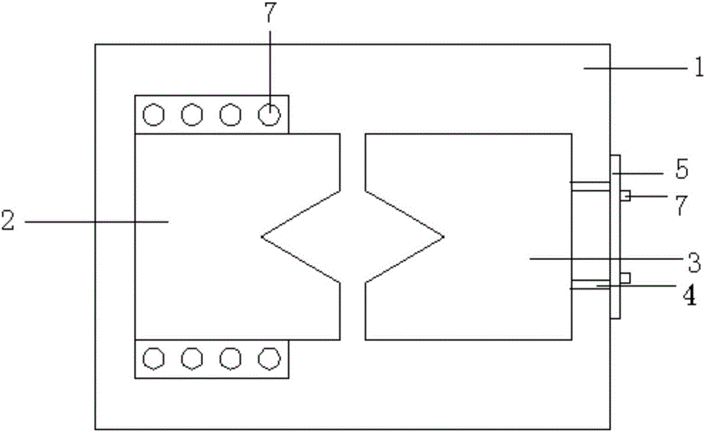
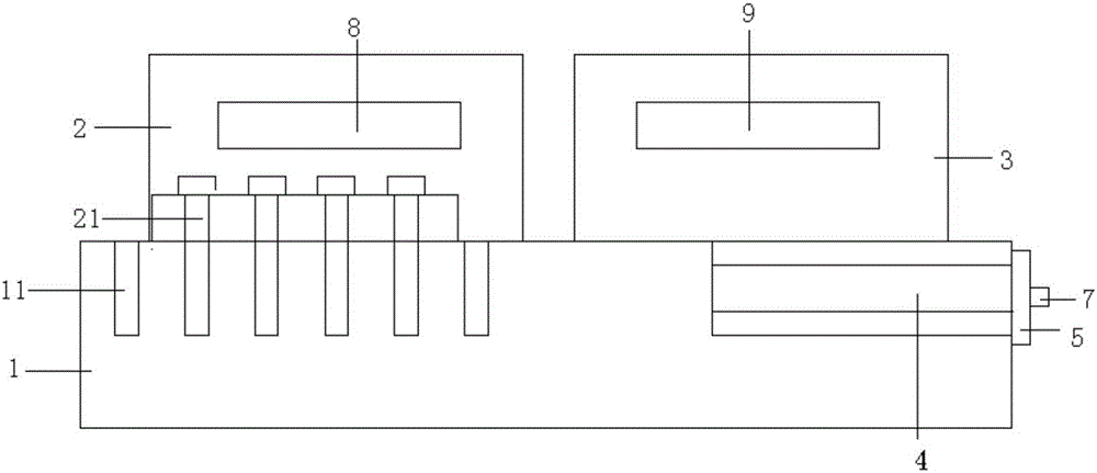
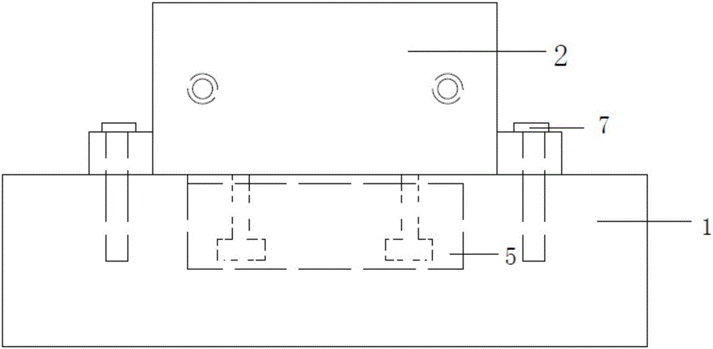
[0030] refer to Figure 1 to Figure 7 , an electromagnetic clamp, including a base 1, the base 1 is oppositely provided with a left clamping part 2 and a right clamping part 3 that are detachably engaged with each other, and the left clamping part 2 and the right clamping part 3 are engaged There is an accommodating space for the workpiece; the left clamping part 2 is detachably connected to the base 1, and the right clamping part 3 is slidably connected to the base 1; the left clamping part Both the holding part 2 and the right holding part 3 have a cavity, and a controller is arranged in the cavity, and a first electromagnet 8 is arranged in the cavity of the left holding part 2. The cavity of the right clamping part 3 is provided with a second electromagnet 9, the winding direction of the coil of the first electromagnet 8 and the second electromagnet 9 is opposite, and the first electromagnet 8 and the second electromagnet 9 are both connected to a controller, and the cont...


PUM


Abstract

The invention discloses an electromagnetic clamp, which comprises a base, and a left clamping part and a right clamping part which are detachably engaged with each other are oppositely arranged on the base, and the left clamping part and the right clamping part are joined together It has an accommodating space for accommodating workpieces; the left clamping part is detachably connected to the base, and the right clamping part is slidingly connected to the base; the left clamping part and the right clamping part Each of the holding parts has a cavity, and a controller is arranged in the cavity, and a first electromagnet is set in the cavity of the left clamping part, and a first electromagnet is set in the cavity of the right clamping part. There is a second electromagnet, the winding directions of the coils of the first electromagnet and the second electromagnet are opposite, and both the first electromagnet and the second electromagnet are connected to the controller , the controller is electrically connected to the power supply. The invention can be used in individual products and mass production, avoiding repeated marking and alignment, improving production efficiency and ensuring the quality of workpieces.

Description

technical field [0001] The invention relates to an electromagnetic clamp. Background technique [0002] Fixtures are an indispensable tool in the machinery industry. With the continuous development of the industry, the fixture industry has become an independent industry in the machine tool industry. There are many types of fixtures on the market today, and every factory needs a huge number of various fixtures. However, after decades of development in fixture design, there are still many problems. [0003] In order to ensure the processing quality of the workpiece, for a mechanism, almost every part needs to design a special fixture, so there will be a variety of fixtures in the workshop tool library and on the ground. The conversion of workpiece production is generally accompanied by the conversion of fixtures, which undoubtedly increases production time. In many cases, the assembly time of the fixture even exceeds the machining time of the workpiece. At present, most of...

Claims


Application Information

Patent Timeline
Patent Type & Authority Patents(China)
IPC IPC(8): B23Q3/15
Inventor 杨亮亮许守金葛宏伟郑斌
Owner 浙江西塘实业有限公司
Why Eureka
Try Eureka