
Insulator string surface cleaning device

A technology for surface cleaning devices and insulator strings, applied in cleaning methods and tools, cleaning methods using tools, overhead line/cable equipment, etc., can solve problems such as difficult to mount stably, inconvenient use, and broken insulators, and achieve reduction Adverse Effects, Ease of Use, Reduced Cleaning Effects

Active Publication Date: 2020-11-13
GUANGDONG POWER GRID CO LTD +1
View PDF15 Cites 12 Cited by
  • Summary
  • Abstract
  • Description
  • Claims
  • Application Information

AI Technical Summary

Problems solved by technology

However, this patent is in the shape of a ring, and when the insulator string is in use, its two ends are connected to the transmission line and the transmission tower respectively. Therefore, when using the device of this patent, the insulator string needs to be removed and inserted from one end of the insulator string The device is inconvenient to use
Moreover, the patent hangs the insulators on the insulator strings by clamping them. The insulators on the insulator strings are connected together by connecting hardware. The carrying cleaning device will affect the connection of the insulators, which may lead to the breakage of the insulator strings; secondly, Some insulators have a small thickness, and clamping the insulator to mount the cleaning device will cause the insulator to break. Fixing the cleaning device with the insulator is easy to damage the paint layer on the surface of the insulator, resulting in insulator failure, shortened service life and other adverse consequences

Method used


Image

  • Insulator string surface cleaning device
  • Insulator string surface cleaning device
  • Insulator string surface cleaning device

Examples


Embodiment Construction

[0029]The specific implementation manners of the present invention will be further described in detail below in conjunction with the accompanying drawings and embodiments. The following examples are used to illustrate the present invention, but are not intended to limit the scope of the present invention.

[0030] In the description of the present invention, it should be noted that the terms "center", "longitudinal", "transverse", "upper", "lower", "front", "rear", "left", "right", " The orientations or positional relationships indicated by "vertical", "horizontal", "top", "bottom", "inner", "outer", etc. are based on the orientation or positional relationships shown in the drawings, and are only for the convenience of describing the present invention and simplifying Describes, but does not indicate or imply that the device or element referred to must have a specific orientation, be constructed in a specific orientation, and operate in a specific orientation, and therefore sho...


PUM


Abstract

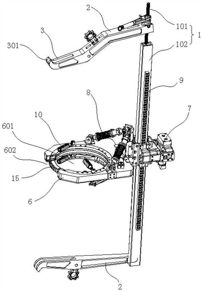
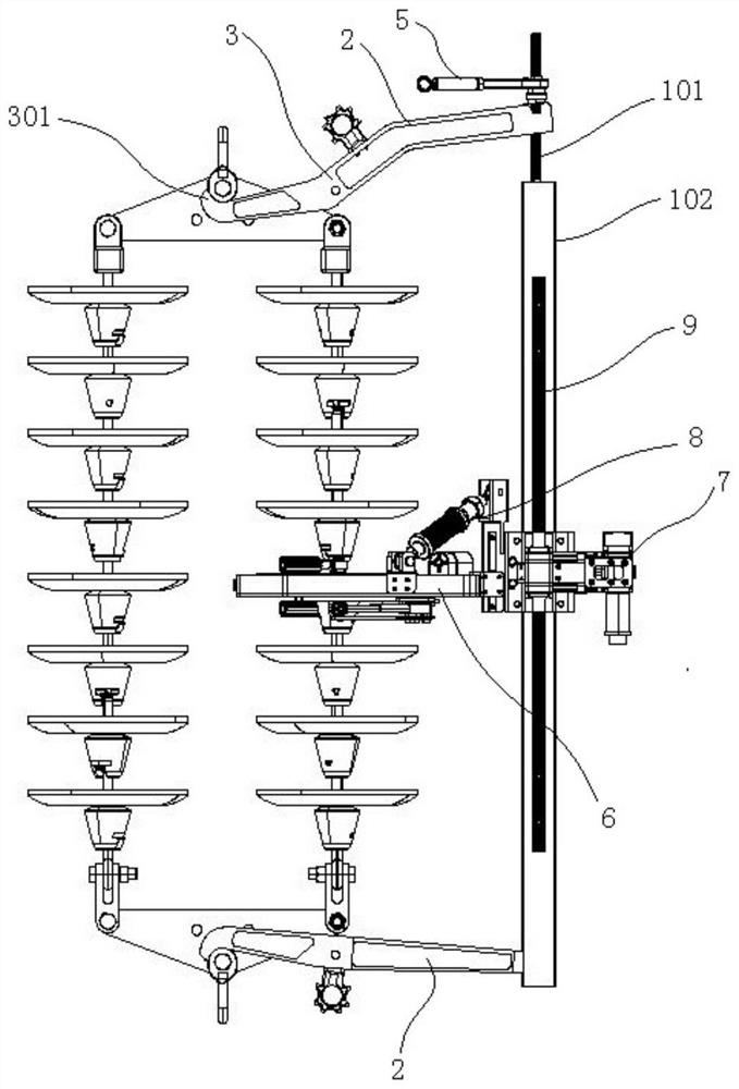
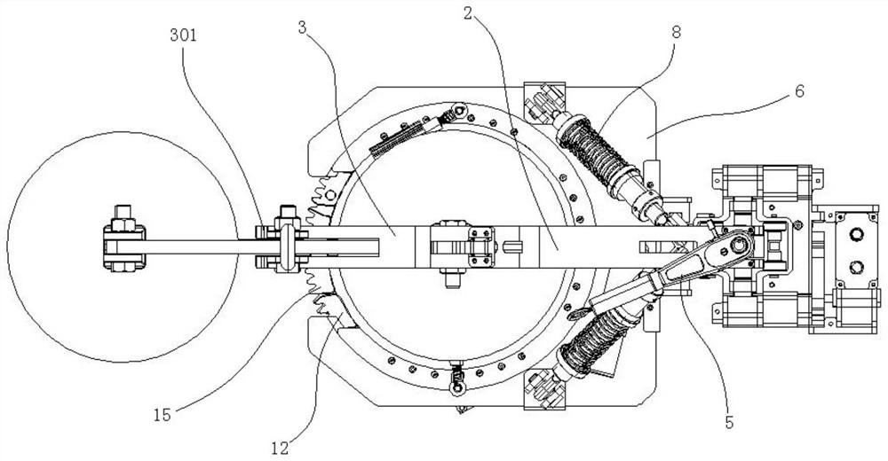
The invention relates to the technical field of power system auxiliary equipment, and discloses an insulator string surface cleaning device. The insulator string surface cleaning device comprises a support, a cleaning mechanism and fixing mechanisms; the fixing mechanisms are arranged at the two ends of the support respectively, the cleaning mechanism is arranged between the two fixing mechanisms,each fixing mechanism comprises a connecting arm, and clamping mechanisms are arranged at one ends of the connecting arms, the clamping mechanisms can move in the length direction of the connecting arms, the other ends of the connecting arms and the cleaning mechanism are connected to the support, the cleaning mechanism and the at least one connecting arm can move in the length direction of the support, the support can be fixed beside an insulator string, stable supporting is provided, and the support is not hung on the insulator string, so that the cleaning mechanism can move in a large space, the optimal cleaning effect is guaranteed, in addition, cleaned dirt can fall off in a space instead of falling on the cleaning device, adverse effects on insulators can be reduced, and adverse effects such as breakage of the insulator string and failure of the insulators are prevented.

Description

technical field [0001] The invention relates to the technical field of power system auxiliary equipment, in particular to an insulator string surface cleaning device. Background technique [0002] With the continuous development of my country's power system, more and more attention has been paid to the safe and stable operation of high-voltage transmission lines. Especially in the high-voltage, ultra-high voltage, and ultra-high voltage transmission systems that have been vigorously developed in recent years, whether the insulator can operate effectively and stably is an important indicator that determines the safe operation of the entire system. In order to ensure the safe operation of the high-voltage transmission line, after the high-voltage transmission line has been in operation for a period of time, it is necessary to test the line, especially the insulation capacity of the insulators, to prevent the occurrence of short circuits. [0003] Because tempered glass insula...

Claims


Application Information

Patent Timeline
Patent Type & Authority Applications(China)
IPC IPC(8): B08B1/04B08B13/00H02G1/02
CPCB08B13/00H02G1/02B08B1/32B08B1/12
Inventor 胡聪王岩武利会石俏杨鑫李浩韩光超时云月
Owner GUANGDONG POWER GRID CO LTD
Learn More