Stainless steel disc polishing equipment

A stainless steel plate and equipment technology, which is applied in grinding/polishing equipment, metal processing equipment, surface polishing machine tools, etc., can solve the problems of hand injury and labor, and achieve the effect of avoiding hand injury

Inactive Publication Date: 2020-11-13
新兴县恒骏达不锈钢有限公司
View PDF11 Cites 11 Cited by
  • Summary
  • Abstract
  • Description
  • Claims
  • Application Information

AI Technical Summary

Problems solved by technology

[0005] In order to overcome the shortcomings of holding the abrasive paper in contact with the stainless steel plate to polish it, the hand is easily injured by contact with the stainless steel plate, and it is more laborious to polish the stainless steel plate by pressing the abrasive paper all the time. The technical problem of the present invention is : To provide a stainless steel plate polishing equipment that can replace manual polishing of stainless steel plates, avoid hand injuries, and save labor

Method used


Image

  • Stainless steel disc polishing equipment
  • Stainless steel disc polishing equipment
  • Stainless steel disc polishing equipment

Examples


Embodiment 1

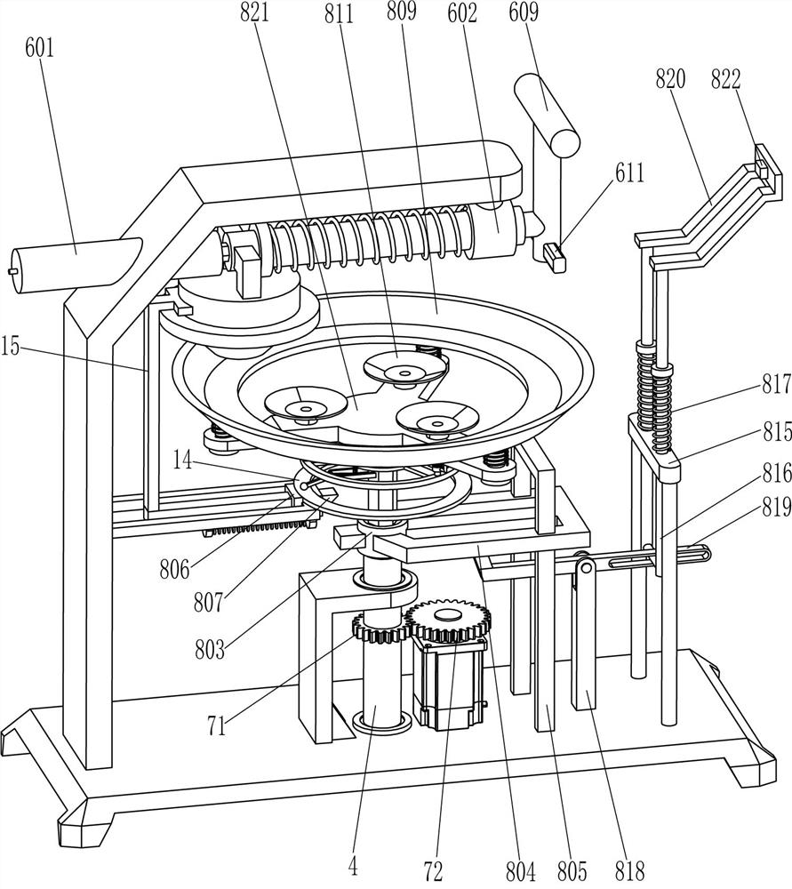
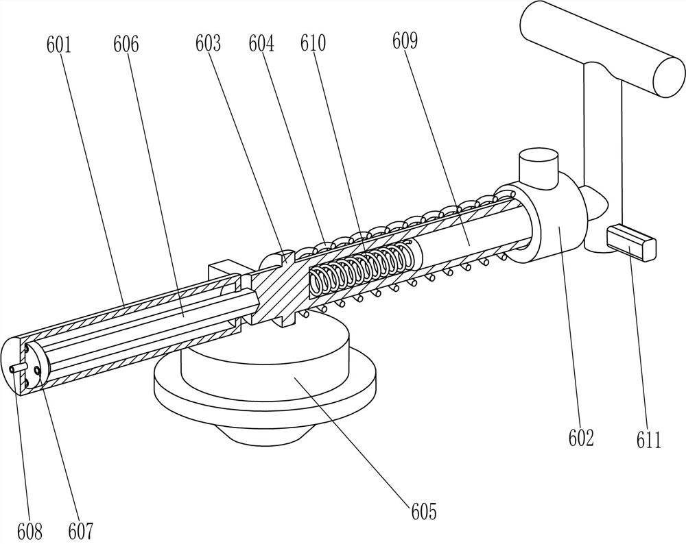
[0023] A stainless steel disc polishing equipment, such as Figure 1-Figure 5 As shown, it includes a base plate 1, a servo motor 2, a support plate 3, a hollow shaft 4, a frame 5, a polishing assembly 6, a spline shaft 7, a first gear 71, a second gear 72 and a rotating assembly 8, and the top of the base plate 1 The left side is fixed with a frame 5, the upper part of the frame 5 is provided with a polishing assembly 6, the top of the bottom plate 1 is connected with a hollow shaft 4 in the middle of the rotation type, and the hollow shaft 4 is slidingly provided with a spline shaft 7, a spline shaft 7 There is a rotating assembly 8 between the top right side of the bottom plate 1, and the rotating assembly 8 cooperates with the polishing assembly 6. The support plate 3 is fixed in the middle of the top left side of the bottom plate 1, and the upper right side of the support plate 3 is rotated with the outer upper part of the hollow shaft 4. connection, the outer middle part...

Embodiment 2

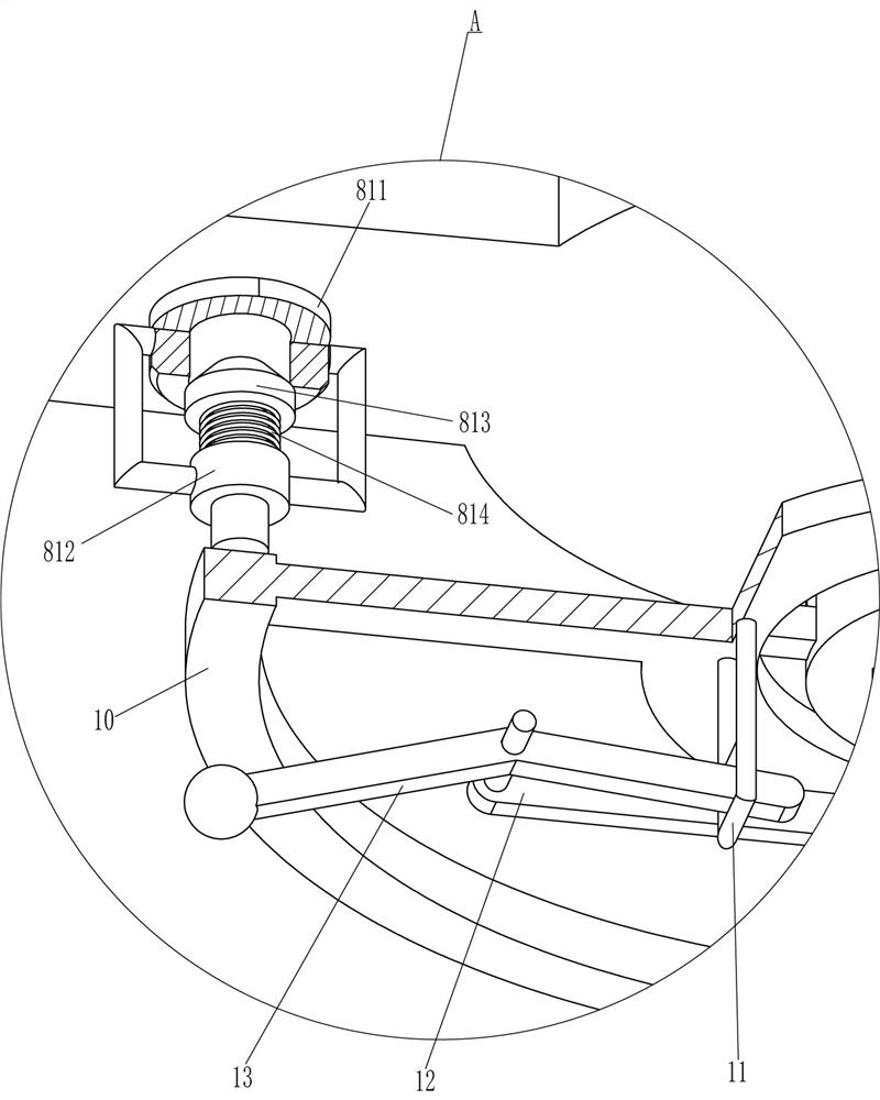
[0030] On the basis of Example 1, such as figure 1 , figure 2 , Figure 4 and Figure 5 As shown, it also includes a sliding frame 10, a fixed rod 11, a support rod 12, a special-shaped rotating rod 13, a fixed ring 14 and a guide sleeve 141. A sliding frame 10 is provided for the sliding type between the circumferential directions. The top of the sliding frame 10 is fixedly connected to the bottom end of the sealing rod 813 in the circumferential direction. The top of the guide sleeve 806 is fixedly connected with a fixed ring 14. 10 is fixedly connected with a fixed rod 11 in the middle on the left side of the bottom, and is fixedly connected with two support rods 12 on the left side of the upper part of the spline shaft 7. Rotating type is connected with special-shaped rotating rod 13 between the sides, and special-shaped rotating rod 13 left ends contact and cooperate with fixed ring 14 tops, and special-shaped rotating rod 13 right-hand ends pass fixed rod 11 bottoms ...

Embodiment 3

[0033] On the basis of embodiment 1 and embodiment 2, such as figure 1 and figure 2 As shown, it also includes a contact rod 15, the top left side of the wedge-shaped rod 807 is fixedly connected with the contact rod 15, and the right end of the contact rod 15 contacts and cooperates with the left side of the grinding block 605.

[0034]Initially, the third spring 808 is in a stretched state. When the operator pulls the pull rod 609 to move to the right, the grinding block 605 moves to the right and breaks away from the contact rod 15. Due to the action of the third spring 808, the wedge-shaped rod 807 moves to the right to drive The contact lever 15 moves to the right to a suitable position. When the grinding block 605 moves to the left and resets, it means that the stainless steel disc is polished. The grinding block 605 resets to drive the contact rod 15 to move to the left to reset, and the contact rod 15 moves to the left to drive the wedge-shaped rod 807 to move to the...


PUM


Abstract

The invention relates to polishing equipment, in particular to stainless steel disc polishing equipment. The technical problem to be solved is how to design the stainless steel disc polishing equipment which can replace manual work to polish a stainless steel disc, prevent hands from being injured and save labor. The stainless steel disc polishing equipment comprises a bottom plate, the middle ofone side of the bottom plate is rotationally connected with a hollow rotating shaft, and a spline shaft is arranged in the hollow rotating shaft in a sliding mode. According to the stainless steel disc polishing equipment, the stainless steel disc is placed in a positioning frame, a pull rod is pulled to move rightwards to the maximum stroke, the positioning frame can drive the stainless steel disc to move upwards to make contact with a grinding block, a servo motor is started, and the positioning frame drives the stainless steel disc to rotate so that polishing can be carried out through thegrinding block, and therefore, hands do not need to hold abrasive paper to make contact with the stainless steel disc to polish the stainless steel disc, the hands are prevented from being injured, and the labor is saved.

Description

technical field [0001] The invention relates to a polishing device, in particular to a stainless steel disc polishing device. Background technique [0002] Stainless steel plate is made of stainless steel, stainless square plate, stainless steel plate is widely used in food, machinery, automobile, home appliances, light industry, electronics, hardware and other industries, mostly used to hold food and factory operating parts. Stainless steel pans are mostly used to hold food for daily use at home. When the stainless steel pans are made, the surface is very rough, so the surface of the stainless steel pans needs to be polished to make the surface of the stainless steel pans smoother for subsequent use. [0003] At present, most of the stainless steel discs are polished by the cooperation of people and machines. First, the stainless steel disc needs to be placed on the rotating machine, and the rotating mechanism drives the stainless steel disc to rotate, and then the stainles...

Claims


Application Information

Patent Timeline
Patent Type & Authority Applications(China)
IPC IPC(8): B24B29/02B24B41/00B24B41/02B24B41/06B24B47/12B24B47/22
CPCB24B29/02B24B41/06B24B41/02B24B47/22B24B47/12B24B41/00
Inventor 林灿燕
Owner 新兴县恒骏达不锈钢有限公司
Why Eureka
Try Eureka